Electrical Interfaces
AGD155 Product Manual Rev.2.2
Page 42
Dedicated digital ground: GND (pin 10 connector X6) must be connected to GND of the
controller/PLC. PE is not used for digital ground.
Each differential input has a 120
Ω
terminator.
Each differential input has a pull-up to 3.3V on its positive pin, and a pull-down to GND on its
negative pin. This ensures that the input is not floating when not connected and that its reading
is known and fixed.
The negative input pin on each differential input also has also a pull-up to 3.3V. This enables use
of a differential input with a single-ended source, by connecting it to the positive input only and
leaving the negative pin disconnected.
The differential inputs can be used with 5V differential sources.
Differential Outputs 1 to 4
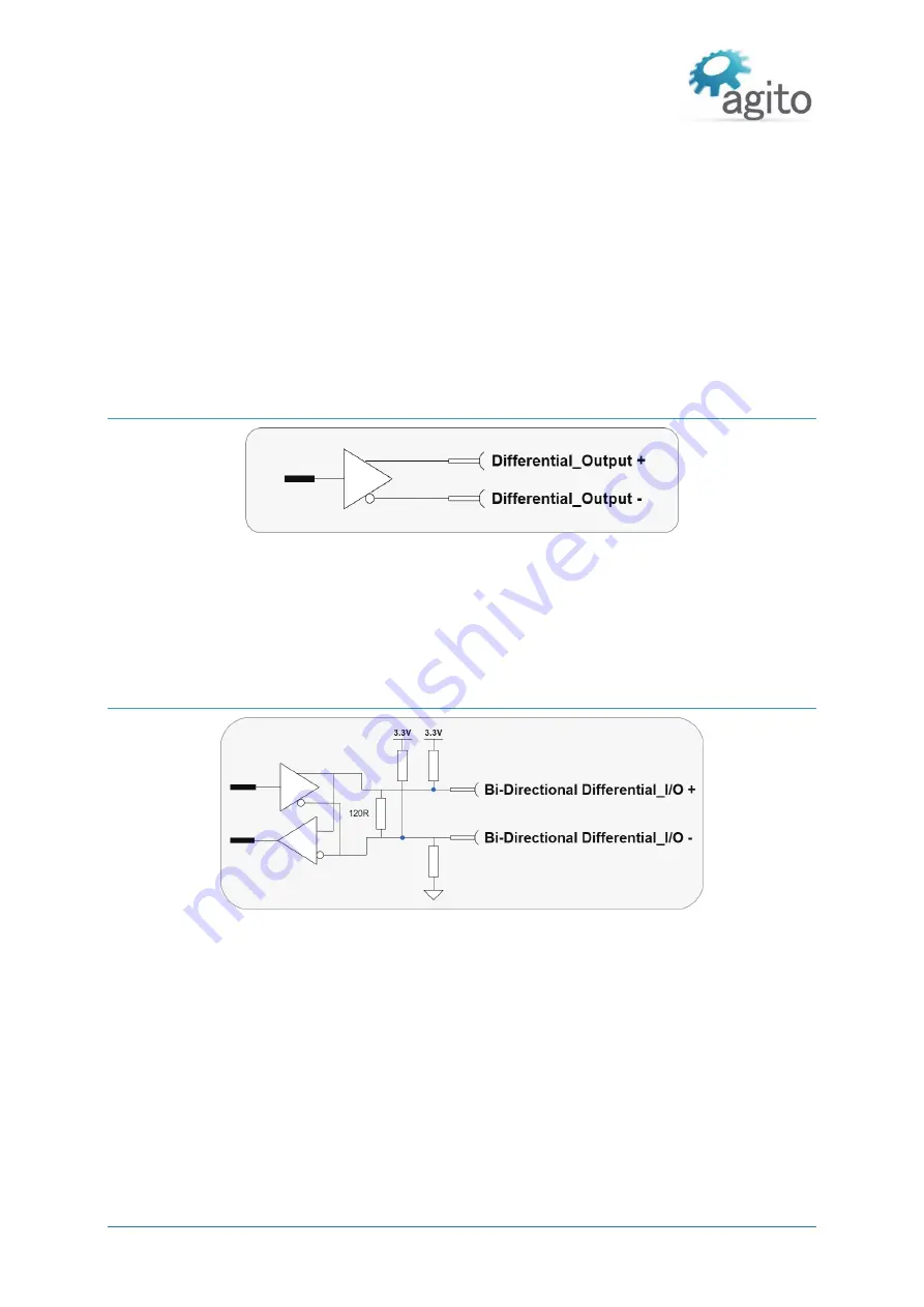
Figure 29. Differential Outputs 1 to 4
Dedicated digital ground: GND (pin 10 connector X6) shall be connected to controller/PLC GND.
PE is not used for digital ground.
The differential outputs are inactive during power on, until they are controlled by the drive
firmware and the user parameters.
Bi-Directional Differential I/O
Figure 30. Bi-Directional Differential I/O
Dedicated digital ground: GND (pin 10 connector X6) must be connected to GND of the
controller/PLC. PE is not used for digital ground.
The bi-directional differential output is configurable by software to be differential output or
differential input.
Both + and - pins are pulled up to 3.3V.
There is a 120
Ω
termination resistor between the + and - pins.


