background image

22

Agilent N5161A/62A/81A/82A/83A MXG Signal Generators Installation Guide

Operation Verification
Frequency Range and Accuracy Check

Spectrum Analyzer Procedure 

(N5161A

1

/62A

1

/81A/82A/83A) 

Test Setup

1.

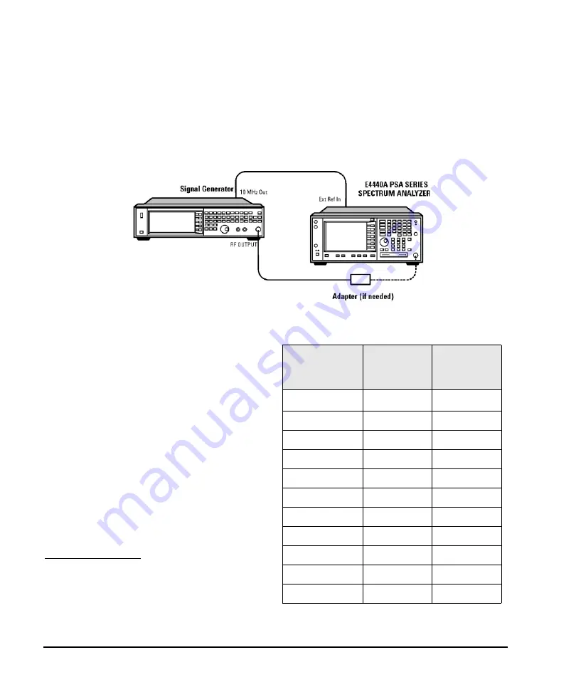
Connect the equipment as shown.

2.

Verify that the spectrum analyzer is locked to the 10 
MHz external reference frequency.

3.

Align the spectrum analyzer: 
Press 

System > Alignment > Align All Now

.

4.

Preset the signal generator: Press 

Preset

.

5.

Turn modulation off: Press the 

Mod On/Off

 so that 

the MOD On/Off LED turns off.

6.

Set the amplitude: 
Press 

Amplitude

 and enter 0 dBm.

7.

Turn RF on: Press 

RF On/Off

 so that the RF On/Off 

LED lights.

8.

Set the frequency: Press 

Frequency

 and set the signal 

generator to the first frequency listed in 

Table 3-3

.

9.

Confirm that the measured frequency is within the 
limits listed in the table.

1.For the N5161A/62A these softkey menus and features 
are only available through the Web-Enabled MXG or 
through SCPI commands. Refer to 

“Configuring the MXG 

ATE” on page 7

, to the 

Programming Guide

, and to the 

SCPI Command Reference

.

10. Repeat step 

8

 and step 

9

 for all of the frequencies in the 

table that are within the frequency range of your signal 
generator.

Table 3-3 Frequency Accuracy Limits

Frequency (MHz)

Limit (Hz)
N5161A/62A/8
1A/82A

Limit (Hz) 
N5183A

0.1 MHz

a

a.

N5181A/82A with s/n prefix: < MY4740, measure at 0.25 MHz

±2

±2

200 MHz

±2

±2

300 MHz

±2

±2

500 MHz

±2

±2

1000 MHz

±2

±2

2000 MHz

±2

±2

3100 MHz

±2

±2

6000 MHz

±2

±4

10 GHz

--

±4

20 GHz

--

±8

32 GHz/40 GHz

--

±16

Summary of Contents for n5181a

Page 1: ...61A 62A 81A 82A 83A MXG Signal Generators Installation Guide Notice This document contains references to Agilent Please note that Agilent s Test and Measurement business has become Keysight Technologies For more information go to www keysight com ...

Page 2: ...t that conflict with these terms the warranty terms in the separate agreement shall control Technology Licenses The hardware and or software described in this document are furnished under a license and may be used or copied only in accordance with the terms of such license Restricted Rights Legend U S Government Restricted Rights Soft ware and technical data rights granted to the federal governmen...

Page 3: ...nfiguring the Display N5181A 82A 83A Only 11 Configuring for Remote Control 12 LAN Configuration 12 GPIB Configuration 13 Ordering Accessories 14 Proper Use and Cleaning 16 Cleaning Suggestions 16 Returning a Signal Generator to Agilent Technologies 16 Contacting Agilent 16 3 Operation Verification Running Self Test 18 Self Test Failure 19 Frequency Range and Accuracy Check 20 Frequency Counter Pr...

Page 4: ...Contents Agilent N5161A 62A 81A 82A 83A MXG Signal Generators Installation Guide vi 4 Regulatory Information Certification 31 Assistance 31 Compliance 31 ...

Page 5: ...og Modulation Option UNT Only Using Pulse Modulation Option UNU Only Basic Digital Operation No BBG Option Installed Basic Digital Operation Option 651 652 654 Adding Real Time Noise to a Signal Option 403 Real Time Phase Noise Impairments Option 432 Custom Digital Modulation Option 431 Multitone and Two Tone Waveform Generator Option 430 Working in a Secure Environment Troubleshooting Programming...

Page 6: ...mmands Arb Commands Real Time Commands N5161A 62A 81A 82A SCPI Command Compatibility N5183A SCPI Command Compatibility Service Guide Troubleshooting Replaceable Parts Assembly Replacement Post Repair Procedures Safety and Regulatory Information Instrument History Key Helpa Key function description Related SCPI commands a Press the Help hardkey and then the key for which you wish help ...

Page 7: ...ons or situations CAUTION Caution calls attention to a condition or situation that could result in damage to or destruction of the signal generator or in the loss of a user s settings or data Do not proceed beyond a caution until you fully understand the indicated conditions NOTE Note calls the user s attention to an important point or special information in the text General Safety Considerations ...

Page 8: ...stralian EMC regulatory information This is the symbol of an Industrial Scientific and Medical Group 1 Class A Product CISPER 11 Clause 4 This symbol marks the on position of the power line switch This symbol marks the standby position of the power line switch This symbol indicates that the input power required is AC This symbol indicates conformance to the standard specificationsa a LXI Class B C...

Page 9: ...E Web Enabled Page on page 8 and to the SCPI Command Reference The MXG ATE blank front panel models N5161A and N5162A signal generators are part of the MXG instrument family and unless otherwise indicated all references to the MXG are inclusive of the MXG ATE instruments Full LXI B feature implementation is only available on instruments with firmware A 01 50 A license may be required to enable thi...

Page 10: ...ded with the shipment by checking the serial number label on the rear of the signal generator and the packing literature included with the shipment 4 The N5183A signal generator is shipped with the adapter options as shown in the following table See also Ordering Accessories on page 14 Signal Generator Physical Characteristics Height 10 16 cm 4 in Width 42 55 cm 16 75 in Depth 48 90 cm 19 25 in We...

Page 11: ...t 4 572 meters 0 to 55 C temperature unless otherwise specified relative humidity type tested at 95 40 C non condensing CAUTION This product is designed for use in INSTALLATION CATEGORY II and POLLUTION DEGREE 2 per IEC 61010 Second Edition and 664 respectively Ventilation Ventilation holes are located on the rear panel and all four sides of the signal generator cover To ensure proper air flow thr...

Page 12: ... provided with a protective earth contact Always use the three prong AC power cord supplied with the signal generator Personal injury can occur if there is any interruption of the protective conductor inside or outside of the signal generator Intentional interruption is prohibited CAUTION The mains wiring and connectors shall be compatible with the connector used in the premise electrical system I...

Page 13: ...age the Programming Guide and to the SCPI Command Reference The MXG ATE N5161A and N5162A are blank front panel versions of the N5181A and N5182A Since the MXG ATE N5161A and N5162A have no front panel softkeys similar the N5181A and N5182A signal generators in order to access the features mentioned in this installation guide two options remain available 1 SCPI commands refer to the SCPI Command R...

Page 14: ... 1 on page 9 For MXG ATEs press the front panel LAN Preset key and wait for the front panel green LAN indicator light to stop blinking It is possible the hostname may have been changed from its default value The MXG ATE hostname is not changed by pressing the LAN Reset key For information on using the MXG s USB port to query its IP address refer to the Agilent Connectivity Guide E2094 90009 or to ...

Page 15: ...block break this Telnet connection e g Internet Explorer 7 When using Internet Explorer as a browser only versions Internet Explorer 7 enable the Web Enabled MXG SCPI feature To operate the signal generator click the keys The Agilent MXG ATE supports LXI Class B functionality For more information on the LXI standards refer to http www lxistandard org home LXI Class B Compliance testing using IEEE ...

Page 16: ... this Page for assistance with the Web Enabled interface 1 From the welcome page of the Web Enabled interface click View Modify Configuration to show the instrument s currently assigned IP address and other parameters 2 Enter the new settings and click Save 3 Click Renew LAN Settings to cause the new settings to take effect Figure 2 2 View Modify Configuration ...

Page 17: ...hrough the Web Enabled MXG or through SCPI commands Refer to the Configuring the MXG ATE on page 7 the Installation Guide the Programming Guide and to the SCPI Command Reference For details on a key press Help and then the desired key Range 0 100 Range 35 55 Range 1 12 hours in 1 hour increments Light Only turns the display light off leaving the text visible at a low intensity Light Text turns the...

Page 18: ...lable through the Web Enabled MXG ATE or through SCPI commands Refer to Configuring the MXG ATE on page 7 to the Programming Guide and to the SCPI Command Reference NOTES Use a 100Base T LAN cable to connect the signal generator to the LAN Use a crossover cable to connect the signal generator directly to a PC For details on using the instrument remotely see the Programming Guide Listed in the Prog...

Page 19: ...rowser to control the signal generator Use a browser to view signal generator files For details on a key press Help and then the desired key Select the desired GPIB language See also the Programming Guide and the SCPI Command Reference NOTES USB is also available It is not shown in the menu because it requires no configuration For details on using the instrument remotely see the Programming Guide ...

Page 20: ...CP N5183A 1CP 5063 9219 5063 9219 5063 9219 5063 9219 5063 9219 Rack Slide Kit N5161A 1CR N5162A 1CR N5181A 1CR N5182A 1CR N5183A 1CR E4406 60115 E4406 60115 E4406 60115 E4406 60115 E4406 60115 Service Kit front panel RF connector N5181A 800 N5182A 800 N5183A 802 N5183A 805 N5181AK 800N 5182AK 800N5 183AK 802 N5183AK 805 Service Kit rear panel RF connector N5161A 801N 5162A 801 N5181A 801 N5182A 8...

Page 21: ...N5180 90001 n c Documentation CD ROMc PDF files Documentation Set Installation Guide Service Guide Text files error messages programming examples N5180 90007 n c a For a description of the contents of each guide and reference see page vii bThese part numbers or options can be ordered after you have received the instrument i e post shipment c Always refer to www agilent com for the most up to date ...

Page 22: ...tentially obstruct ventilation periodically clean the instrument s cover Use a dry cloth or a cloth slightly dampened with water to clean the external case parts Returning a Signal Generator to Agilent Technologies 1 Gather as much information as possible about the signal generator s problem 2 Contact Agilent using the phone number that is specific to your geographic location These phone numbers a...

Page 23: ... of the MXG instrument family and unless otherwise indicated all references to the MXG are inclusive of the MXG ATE instruments For the instrument to meet performance specifications allow a warm up period of 45 minutes within an operational temperature range of 0 to 55 C For more information refer to the MXG signal generator Data Sheet Operation verification is a series of tests used to confirm th...

Page 24: ...plete Not all tests have been run 3 Press Run Complete Self Test An activity bar displays on the screen indicating the test progress If you press Abort while self test is running the following message displays The current status of the self test is Incomplete Not all tests have been run When self test completes one of the following messages displays The current status of the self test is Passed Th...

Page 25: ...nerator requires service If you are unable to service the signal generator send it to an Agilent service center for repair Include a detailed description of the most significant failure root failure and any displayed error messages See Viewing Test Results on page 19 for information about viewing detailed self test results See Returning a Signal Generator to Agilent Technologies on page 16 for ret...

Page 26: ...limits of the signal generator This test can be performed with either a frequency counter or a spectrum analyzer Table 3 1 Recommended Equipment for Checking N5161A 62A 81A 82A 83A Frequency Range and Accuracy Test Equipment Recommended Model Frequency Counter N5161A 62A 81A 82A Agilent 53131A or 53132A with Option 010 and 050 or 124 Spectrum Analyzer N5161A 62A 81A 82A N5183A Option 520 N5183A Op...

Page 27: ...e the arrow keys to set the value 8 Set the frequency Press Frequency and set the signal generator to the first frequency listed in Table 3 2 9 Confirm that the measured frequency is within the limits listed 1 For the N5161A 62A these softkey menus and features are only available through the Web Enabled MXG or through SCPI commands Refer to Configuring the MXG ATE on page 7 to the Programming Guid...

Page 28: ...et the frequency Press Frequency and set the signal generator to the first frequency listed in Table 3 3 9 Confirm that the measured frequency is within the limits listed in the table 1 For the N5161A 62A these softkey menus and features are only available through the Web Enabled MXG or through SCPI commands Refer to Configuring the MXG ATE on page 7 to the Programming Guide and to the SCPI Comman...

Page 29: ...l reference Checking the Output Power This test verifies that the CW output power from the signal generator is within defined limits The following table lists the preferred equipment for this test N5161A 81A Test Procedure on page 24 N5162A 82A Test Procedure on page 25 N5183A Test Procedure on page 27 If this test fails refer to Troubleshooting Problems with the Output Power Check on page 29 for ...

Page 30: ...ac button on the power meter b Select a power meter channel if applicable 1 For the N5161A 62A these softkey menus and features are only available through the Web Enabled MXG or through SCPI commands Refer to the Programming Guide or to the SCPI Command Reference c Use the arrow keys to enter the frequency at which to measure the power 9 Measure the output power level 10 Repeat steps 6 through 9 t...

Page 31: ...us and features are only available through the Web Enabled MXG or through SCPI commands Refer to the Programming Guide or to the SCPI Command Reference Press Amplitude 7 dBm 8 Configure the power meter as follows a On the power meter press the Frequency Cal Fac button b If applicable select a power meter channel c Use the arrow keys to enter the frequency at which to measure the power 9 Measure th...

Page 32: ...s Frequency 125 MHz 15 Set the amplitude to 7 dBm Press Amplitude 7 dBm 16 Configure the power meter as follows a On the power meter press the Frequency Cal Fac button b Select a power meter channel if applicable c Use the arrow keys to enter the frequency at which to measure the power 17 Measure the output power 18 Repeat steps 14 through 17 for the remaining frequencies listed in Table 3 6 and c...

Page 33: ... c Use the arrow keys to enter the frequency at which to measure the power 9 Measure the output power level 10 Repeat steps 6 through 9 to measure power at each of the 15 frequencies listed in Table 3 8 11 Confirm that the measured power levels are within the limits listed in the table Refer to Table 3 7 on page 27 Refer to Table 3 7 Table 3 7 Power Sensors by Frequency and Options N5183A Frequenc...

Page 34: ...28 Agilent N5161A 62A 81A 82A 83A MXG Signal Generators Installation Guide Operation Verification Checking the Output Power b For questions around measurement uncertainty refer to the Data Sheet ...

Page 35: ...t Power Check Verify that you are using the appropriate power sensor Normally power sensor calibration factors are automatically downloaded to the power meter when the power meter turns on If this does not occur manually enter the correct calibration factors for the power sensor you are using Verify that the power sensor is properly calibrated to the power meter ...

Page 36: ...30 Agilent N5161A 62A 81A 82A 83A MXG Signal Generators Installation Guide Operation Verification Checking the Output Power ...

Page 37: ...nd EMC regulations and directives A copy of the manufacturer s Declaration of Conformity for this product s can be obtained by contacting your local Agilent Technologies sales representative EMC Complies with the essential requirements of the European EMC Directive as well as current editions of the following standards dates and editions are cited in the Declaration of Conformity IEC EN 61326 1 CI...

Page 38: ...atory Information Compliance Acoustic statement European Machinery Directive Acoustic noise emission LpA 70 dB Operator position Normal operation mode per ISO 7779 To find a current Declaration of Conformity for a specific Keysight product go to http www keysight com go conformity ...

Page 39: ...ame setting 12 humidity requirements 5 I ICES symbol 2 IEC Publication 61010 31 inspection shipping container 4 instrument warm up 17 interface GPIB 13 interface LAN 12 IP address setting 12 ISM1 A symbol 2 L LAN configuration 12 line setting requirements 5 LXI standard specifications symbol 2 M manuals ordering 14 MXG ATE configuring 7 web enabled 7 web enabled accessing 8 10 O operation verifica...

Page 40: ...61A 62A 81A 82A 83A MXG Signal Generators Installation Guide Index V ventilation requirements 5 verification operation 17 voltage requirements 5 VXI 11 enabling 13 W warnings 1 web server 13 weight signal generator 4 ...

Reviews: