Agilent Technologies J-BERT N4903A Getting Started Download Page 11

11

Modifying the Test Setup

Inserting Errors

You can add a single bit error to the data stream by pressing
the

button.

Error Add

To provide comparable results, you can run tests over a longer time
and collect the measured data:

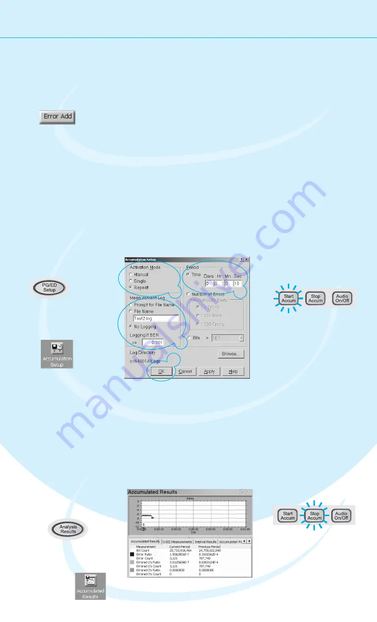
Setting up Error Accumulation

Accumulation Results

View the accumulated results:

You could also loosen the data
cable and wiggle it carefully.
Watch how the BER changes.

The pattern generator can also be set up
to insert a specified BER in the data
stream. This can, for example, be used
for testing error correction algorithms.

Select

,

because we do not
need a measurement
log file now.

No Logging

Select a

of

10 seconds as the
measurement period.

Time

3

4

5

Press the

button to

start accumulating.

Start

Accum

Press the
button twice to switch to
the

tab.

Analysis Results

Results

Switch to the
Accumulated Results.

1

2

Here you can view all statistics
measured during the current and
the previous measurement.

To stop the J-BERT from
collecting any more data,
press the

button.

Stop Accum

Select the activation
mode

to run

repeated tests.

Repeat

6

7

Press

.

OK

Open the

dialog box.

Accumulation

Setup

Press the
button twice to switch
to the error detector setup.

PG/ED Setup

1

2

3

4

5

6

Summary of Contents for J-BERT N4903A

Page 1: ...mation on the J BERT check out the Online Help The Help also offers printable versions of the User Guide and the Programming Guide You only need a few minutes to get started with the J BERT This Getti...

Page 2: ...specified in the operation instructions All Light Emitting Diodes LEDs used in this product are Class 1 LEDs as per IEC 60825 1 Environmental Conditions Verify that all safety precautions are taken Th...

Page 3: ...m any single phase AC power source supplying 100 240 V in the frequency range from 47 63 Hz The maximum power consumption is 450 VA with all options installed The power supply automatically adapts to...

Page 4: ...PS 2 Mouse green Serial Port 1 Parallel Port VGA Monitor Ethernet Port 1 2 Audio Line Output Jack Audio Microphone Input Jack Diagnostic LED Stack USB 2 0 Channel 0 3 The Agilent J BERT is available i...

Page 5: ...values by hand or the large knob to adjust values You can also use the knobs at the bottom of the instrument to change certain frequently used values in run time Navigating the GUI The menu buttons al...

Page 6: ...tput Reset the instrument This sets all voltages and parameters to default values Now select the logic family LVDS for the data and clock port Check the values to make sure you can t damage your devic...

Page 7: ...e used for the test Select the Pattern Press the button to switch to the pattern editor Pattern Setup Open the dialog box Pattern Select Select the pattern type 2 n 1 PRBS Select the pattern size 2 31...

Page 8: ...etector uses the clock from the pattern generator 2 PG Clock Out PG Data Out ED Data In ED Clock In Press the button twice to switch to the error detector setup PG ED Setup Click the button Edit Set t...

Page 9: ...e sure that and are selected Normal Sync Mode Automatic Sync 1 2 Switch to the Sampling Point Setup Press the button to measure the eye diagram and to position the sampling point at the center of the...

Page 10: ...to move the sampling point horizontally Data In Delay You can see how the BER increases when measuring at the edge of the eye 1 2 Viewing Eye Results Now let s check the resulting eye Press the butto...

Page 11: ...le be used for testing error correction algorithms Select because we do not need a measurement log file now No Logging Select a of 10 seconds as the measurement period Time 3 4 5 Press the button to s...

Page 12: ...ument The software will automatically recognize the new component and provide the Interface Channel Icon and according setup functions in the window Jitter Perform the regular shutdown procedure provi...

Reviews: