204
1100 Series WS MWS Reference Manual
6
Introduction to the Well-plate Sampler
Sampling Unit
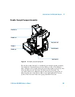
The sampling unit consists of subsystems as well. The main carrier part is a
die casting part which carries the following functional elements.
Analytical head
The analytical head is driven by the stepper motor connected to the drive shaft
by a toothed belt. The drive nut on the spindle converts the circular movement
of the spindle to linear motion. The drive nut pushes the sapphire plunger
against the tension of the spring into the analytical head. The base of the
plunger sits on the large bearing of the drive nut, which ensures the plunger is
always centered. A ceramic ring guides the movement of the plunger in the
analytical head. The home position of the plunger is sensed by an infra-red
sensor on the sampling unit flex board, while the sample volume is determined
by counting the number of steps from the home position (7 nl/motor step). The
backward movement of the plunger (driven by the spring) draws sample from
the vial.
To reduce potential user mistakes different versions of analytical heads are
recognized by RF-tags sitting on the exchangeable assembly.
Summary of Contents for G1367A
Page 1: ...s1 Agilent 1100 Series Well plate Sampler Micro Well plate Sampler Reference Manual...
Page 4: ...4 1100 Series WS MWS Reference Manual...
Page 42: ...42 1100 Series WS MWS Reference Manual 1 Installing the Sampler...
Page 156: ...156 1100 Series WS MWS Reference Manual 4 Repairing the Sampler...
Page 196: ...196 1100 Series WS MWS Reference Manual 5 Parts and Materials...
Page 214: ...214 1100 Series WS MWS Reference Manual 6 Introduction to the Well plate Sampler...
Page 240: ...240 1100 Series WS MWS Reference Manual 7 Theory of Operation...
Page 276: ...276 1100 Series WS MWS Reference Manual 9 Specifications...
Page 284: ...284 1100 Series WS MWS Reference Manual Index...
Page 285: ......


