


1
Getting Started
16
E4418B Power Meter User’s Guide
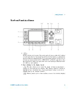
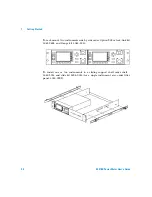
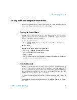
The Rear Panel at a Glance
1
Channel A (Option 002 or 003 only)
2
Power Ref (Option 003 only)
The power reference output is a 50
Ω
type- N connector. The output signal is
used for calibrating the sensor meter combination.
3
Recorder Output
This output produces a DC voltage that corresponds to the power level of
the channel input. Refer to
on page 86 for further
information.
4
Power socket
This power meter has an auto configuring power supply. This allows it to
operate over a range of voltages without manually being set to a certain
voltage.
5
Fuse
An F3.15AH fuse is installed for all voltage supplies.
6
GPIB
This connector allows the power meter to be controlled remotely using the
General Purpose Interface Bus.
7
RS232/422
This connector allows the power meter to be controlled remotely using
either the RS232 or RS422 serial interface standards.
1
2
3
4
5
6
7
9
8
10
N279
Summary of Contents for E4418B
Page 1: ...Agilent Technologies Agilent E4418B Power Meter User s Guide ...
Page 14: ...xiv E4418B Power Meter User s Guide THIS PAGE HAS BEEN INTENTIONALLY LEFT BLANK ...
Page 20: ...xx E4418B Power Meter User s Guide THIS PAGE HAS BEEN INTENTIONALLY LEFT BLANK ...
Page 22: ...xxii E4418B Power Meter User s Guide THIS PAGE HAS BEEN INTENTIONALLY LEFT BLANK ...
Page 24: ...xxiv E4418B Power Meter User s Guide THIS PAGE HAS BEEN INTENTIONALLY LEFT BLANK ...
Page 113: ...Power Meter Operation 2 E4418B Power Meter User s Guide 89 Figure 2 21 Save Recall Screen ...


