


2
Power Meter Operation
86
E4418B Power Meter User’s Guide
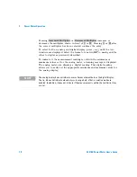
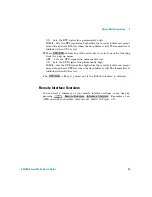
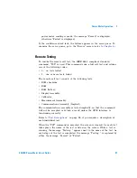
Recorder Output
The rear panel Recorder Output connector produces a DC voltage that
corresponds to the power level in Watts of the channel, depending on the
measurement mode. This DC voltage ranges from 0 to +1 Vdc. The output
impedance is typically 1 kW . Channel and display offsets and duty cycle
have no effect on the Recorder Output.
For example, the Recorder Output can be used to;
•
record swept measurements on an X- Y recorder
•
level an output from a source using external leveling or
•
monitor the output power on a strip chart recorder. A setup for
recording swept measurements is shown in
.
See
for details on which power meter functions are
implemented in the recorder output.
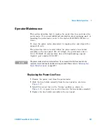
Figure 2-20
Test Setup for Recording Swept Measurements
To access the “Recorder” menu, press
,
,
.
This menu allows you to switch the Recorder Output signal either on or
off. The
and
softkeys allow you to enter the input
power level that you want to represent the 1 Vdc maximum and 0 Vdc
minimum output voltage of the Recorder Output.
Device
Power Meter
CHANNEL A
INPUT
OUT
X-Y Recorder
Swept Source
Under Test
IN
RF OUT
SWEEP
OUT
X-AXIS (FREQUENCY)
Y-AXIS (POWER)
RECORDER
OUTPUT
Recorder Output
Max Power
Min Power
Summary of Contents for E4418B
Page 1: ...Agilent Technologies Agilent E4418B Power Meter User s Guide ...
Page 14: ...xiv E4418B Power Meter User s Guide THIS PAGE HAS BEEN INTENTIONALLY LEFT BLANK ...
Page 20: ...xx E4418B Power Meter User s Guide THIS PAGE HAS BEEN INTENTIONALLY LEFT BLANK ...
Page 22: ...xxii E4418B Power Meter User s Guide THIS PAGE HAS BEEN INTENTIONALLY LEFT BLANK ...
Page 24: ...xxiv E4418B Power Meter User s Guide THIS PAGE HAS BEEN INTENTIONALLY LEFT BLANK ...
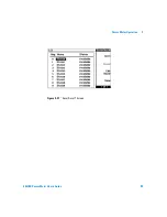
Page 113: ...Power Meter Operation 2 E4418B Power Meter User s Guide 89 Figure 2 21 Save Recall Screen ...


