


Chapter 3 Front-Panel Operation and Features
Constant Voltage Operation
40
Constant Voltage Operation
To set up the power supply for constant voltage (CV) operation, proceed as
follows.
•
Front-panel operation:
1 Connect a load to the output terminals.
With power-off, connect a load to the (+) and (-) output terminals.
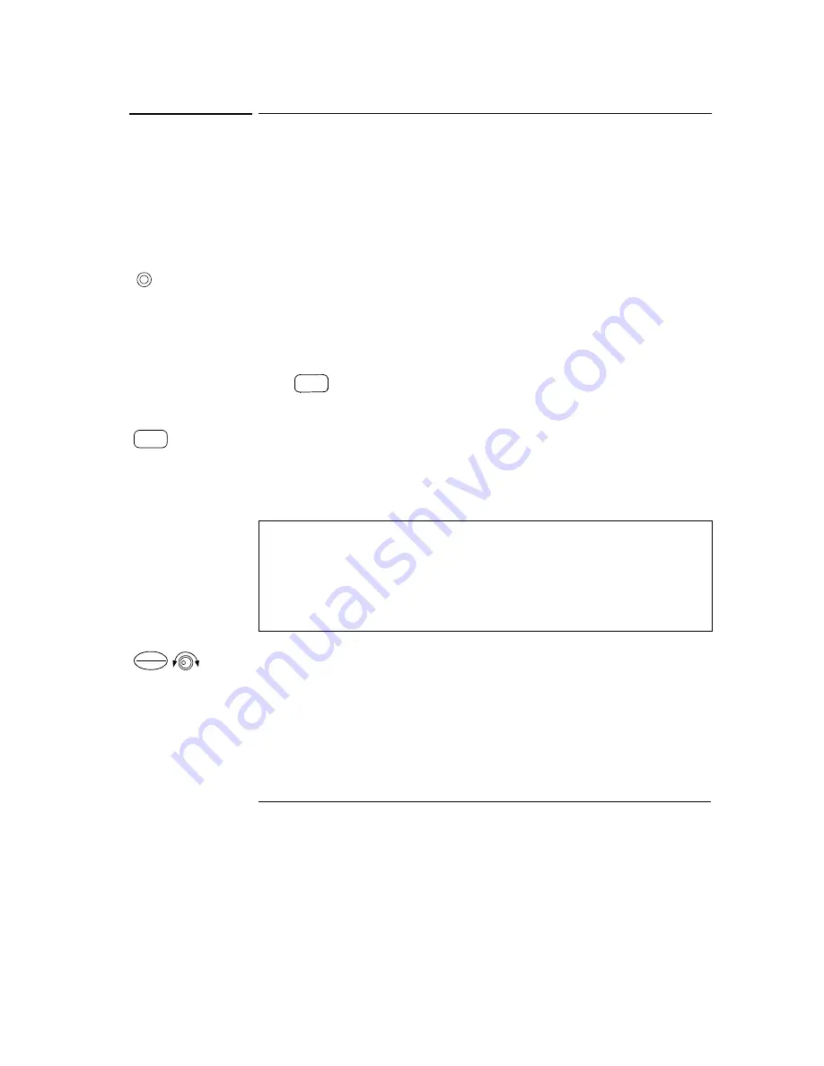
2 Turn on the power supply.
The power supply will go into the
power-on / reset
state; the output is disabled
(the
OFF
annunciator turns on); its low voltage range is selected (annunciator
for the range presently selected turns on, for example, the
8V
annunciator turns
on for the E3646A model); and the knob is selected for
voltage
control. At
power-on, the output1 is selected and the
OUT1
annunciator turns on.
Press
to operate the power supply in the high voltage range before
proceeding to the next step. The
20V
or
60V
annunciator turns on depending
on which power supply you are using.
3 Set the display to the limit mode.
Notice that the
Limit
annunciator flashes, indicating that the display is in the
limit
mode. When the display is in the
limit
mode, you can see the voltage and
current limit values of the power supply.
4 Adjust the knob for the desired
current
limit.
Check that the
Limit
annunciator still flashes. Set the knob for
current
control.
The flashing digit can be changed using the resolution selection keys and the
flashing digit can be adjusted by turning the knob. Adjust the knob to the
desired current limit.
1
You can use the resolution selection keys to move the flashing digit to the
right or left when setting current.
In
constant voltage
mode, the voltage values between the meter and
limit modes are the same, but the current values are not. Moreover, if the
display is in the meter mode, you cannot see the change of current limit
value when adjusting the knob. We recommend that you should set the
display to “limit” mode to see the change of current limit value in the
constant voltage mode whenever adjusting the knob.
Power
High
Display
Limit
Current
Voltage
1
Summary of Contents for E364XA Series
Page 9: ...8...
Page 15: ...14 Contents Contents...
Page 16: ...1 Quick Start...
Page 26: ...2 General Information...
Page 38: ...3 Front Panel Operation and Features...
Page 70: ...4 Remote Interface Reference...
Page 122: ...5 Error Messages...
Page 133: ...Chapter 5 Error Messages Calibration Errors 132...
Page 134: ...6 Application Programs...
Page 145: ...Chapter 6 Application Programs Example Program for Excel 97 144...
Page 146: ...7 Tutorial...
Page 157: ...Chapter 7 Tutorial Remote Programming 156...
Page 158: ...8 Specifications...
Page 166: ...Appendix Service Information...
Page 175: ...Appendix Service Information General Disassembly 174 General Disassembly...
Page 207: ......
Page 208: ......
Page 209: ......
Page 210: ......
Page 211: ......
Page 212: ......
Page 213: ......
Page 214: ......
Page 215: ......
Page 216: ......
Page 217: ......
Page 218: ......


