background image


General Information and Safety Practices and Hazards 

Agilent Cary 60 Spectrophotometer User’s Guide 

11 

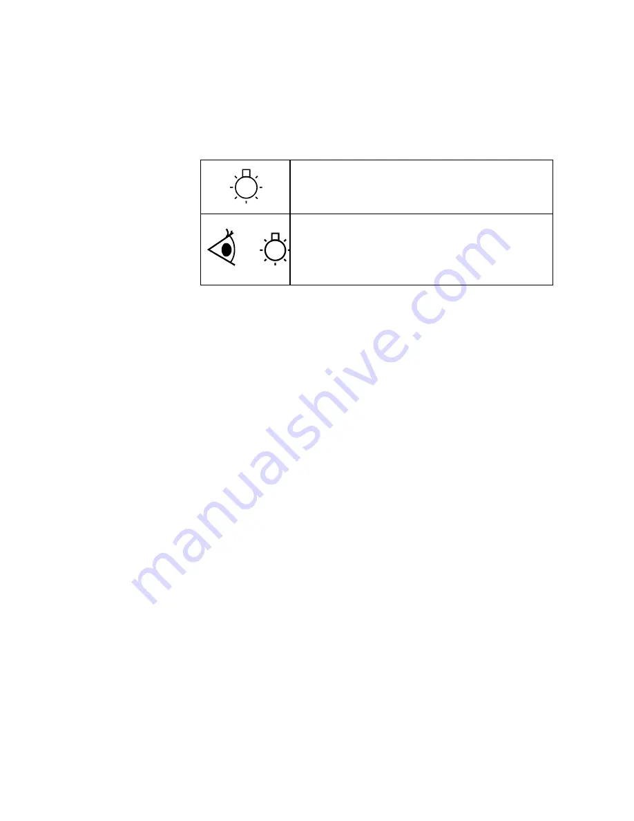
The following symbols appear on the instrument for your 
information: 


Indicates high voltage Xenon flash lamp present. 

Indicates viewing hole to check the operation of the Xenon 
flash lamp. 

CE Compliance 

Your Agilent Cary 60 spectrophotometer has been designed to 
comply with the requirements of the Electromagnetic Compatibility 
(EMC) Directive and the Low Voltage (electrical safety) Directive 
(commonly referred to as the LVD) of the European Union. Agilent 
has confirmed that each product complies with the relevant 
Directives by testing a prototype against the prescribed EN 
(European Norm) standards. 

Proof that a product complies with these directives is indicated by: 


the CE Marking appearing on the rear of the product, and 


the documentation package that accompanies the product 
containing a copy of the Declaration of Conformity. The 
Declaration of Conformity is the legal declaration by Agilent that 
the product complies with the directives listed above, and shows 
the EN standards to which the product was tested to 
demonstrate compliance. 

Summary of Contents for Cary 60

Page 1: ...Agilent Cary 60 Spectrophotometer User s Guide ...

Page 2: ... this document or of any information contained herein Should Agilent and the user have a separate written agreement with warranty terms covering the material in this document that conflict with these terms the warranty terms in the separate agreement shall control Technology Licenses The hardware and or software described in this document are furnished under a license and may be used or copied onl...

Page 3: ...mp Module 8 Modules Covers and Panels 9 Other Precautions 9 Warning and Other Symbols 10 CE Compliance 11 Electromagnetic Compatibility 12 EN55011 CISPR11 12 2 Specifications 15 Measurement Category 15 Pollution Degree 15 Environmental Conditions 16 Weights and Dimensions 17 Electrical Specifications 18 Mains Supply 18 Computer Requirements 19 3 Installation 21 Installation 21 ...

Page 4: ...Running the Tutorials 26 Cell Holder 27 Installation 27 Alignment 29 Other Sample Holders 30 Installing Accessories 30 4 Introduction 31 Instrument Overview 31 Indicator Lamp 32 Connections 33 Using the Software 33 5 Troubleshooting 35 Access Denied 35 Problem 35 Solution 35 No Green Light Indicating that the Cary 60 is Powered 37 Problem 37 Solution 37 Start Button Replaced with Connect Button 37...

Page 5: ... Fluctuates Wildly During a Scan 39 Problem 39 Solution 39 Instrument Performance Testing 40 Problem 40 Solution 40 Wavelength Calibration 41 Problem 41 Solution 41 Front Panel LED Troubleshooting 41 LED Won t Light Up 41 Solid Red LED 41 Flashing Red LED 42 6 Maintenance and Spare Parts 43 Maintenance 43 Spare Parts 44 ...

Page 6: ...Contents 6 Agilent Cary 60 Spectrophotometer User s Guide This page is intentionally left blank ...

Page 7: ...the documentation both hard copy and online provided with your instrument and accessories to help you safely operate the instrument and accessories Before using the instrument or accessories you must thoroughly read these safety practices ALWAYS operate the instrument and accessories in accordance with these safety practices User Documentation You have been provided with the following documentatio...

Page 8: ... From the Edit menu choose Copy ALL CAPITALS indicate keyboard commands For example Press ENTER and Press SHIFT F3 NOTE Throughout this manual UV Dissolution and UV Fiber Optic Dissolution users should replace Cary WinUV Software with UV Dissolution Software or UV Fiber Optic Dissolution Software respectively Notes and Tips A Note is used to give advice or information A Tip is used to give practic...

Page 9: ... service engineers Other Precautions Do not block any ventilation grills present on the computer Consult the manuals supplied with your PC monitor and printer plotter for their specific ventilation requirements Use of the Cary 60 system and accessories may involve materials solvents and solutions that are flammable corrosive toxic or otherwise hazardous Careless improper or unskilled use of such m...

Page 10: ...wn A triangular symbol indicates a warning The meanings of the symbols that may appear alongside warnings in the documentation or on the instrument itself are as follows Electrical shock Eye hazard Heavy weight danger to feet Heavy weight danger to hands The following symbol may be used on warning labels attached to the instrument When you see this symbol refer to the relevant operation or service...

Page 11: ...trical safety Directive commonly referred to as the LVD of the European Union Agilent has confirmed that each product complies with the relevant Directives by testing a prototype against the prescribed EN European Norm standards Proof that a product complies with these directives is indicated by the CE Marking appearing on the rear of the product and the documentation package that accompanies the ...

Page 12: ...le for use in all establishments other than domestic and those directly connected to a low voltage power supply network which supplies buildings used for domestic purposes This device complies with the requirements of CISPR11 Group 1 Class A as radiation professional equipment Therefore there may be potential difficulties in ensuring electromagnetic compatibility in other environments due to condu...

Page 13: ...he device away from the radio or television 3 Plug the device into a different electrical outlet so that the device and the radio or television are on separate electrical circuits 4 Make sure that all peripheral devices are also certified 5 Make sure that appropriate cables are used to connect the device to peripheral equipment 6 Consult your equipment dealer Agilent Technologies or an experienced...

Page 14: ...General Information and Safety Practices and Hazards 14 Agilent Cary 60 Spectrophotometer User s Guide This page is intentionally left blank ...

Page 15: ...tions 16 Weights and Dimensions 17 Electrical Specifications 18 Computer Requirements 19 Measurement Category The Measurement category is IEC61010 I Do not to use this equipment for measurements within measurement categories II III and IV Pollution Degree The pollution degree is IEC61010 2 Pollution degree 2 applies to a normal indoor atmosphere ...

Page 16: ...n 20 and 25 C and be held constant to within 2 C throughout the entire working day The area should have a dust free low humidity atmosphere Air conditioning is recommended The room should be temperature controlled if your analyses are particularly sensitive Condition Altitude m ft Temp C F Humidity RH non condensing Non operating transport 0 4600 0 15000 40 70 40 158 90 Operating within performanc...

Page 17: ...D monitor The workbench should be about 90 cm 36 in high Remember to provide space for the computer monitor and printer To avoid damage through spillage of solutions and samples being analyzed the worktops should be covered with a material that is corrosion resistant and impervious to liquids Allow at least two inches of space on both sides and six inches at the rear of the system to permit free a...

Page 18: ...tions imposed by local authorities responsible for the supply of electrical energy to the workplace WARNING Shock Hazard Danger of electrocution Good electrical grounding is essential to avoid potentially serious shock hazards A 3 wire outlet with ground connection must be provided for the Cary 60 Make certain that power outlets are earth grounded at the grounding pin All power supplies for the Ca...

Page 19: ...s the system that was used during evaluations Manufacturer Hewlett Packard Model HP Desktop Small Form Factor Processor Intel Core 2 Duo E8500 Processor Memory 2 GB PC3 10600 Memory 2x1 GB Storage 250 GB SATA 3 5 1st Hard Drive Graphics Integrated Intel Graphics Media Accelerator 4500 Communications Integrated Intel 82567LM Gigabit Optical Drive 16x SATA SuperMulti LightScribe DVD RW Audio Realtek...

Page 20: ...Specifications 20 Agilent Cary 60 Spectrophotometer User s Guide This page is intentionally left blank ...

Page 21: ...ctrical power supplies are available see Page 18 A computer that meets requirements is available see Page 19 A working Microsoft Windows operating system is installed on the computer For instructions on installing this refer to the documentation supplied with the operating system The Cary 60 has been unpacked see Page 22 Installation The Agilent Cary 60 spectrophotometer is designed to be complete...

Page 22: ...ivery take the equipment to the installation site Agilent instruments are inherently robust and the packaging is designed to prevent internal damage However the contents form part of a precision measuring system and all packages should be handled with care In transit sharp jolts must be avoided and the packages should not be inverted or tilted unnecessarily Markings on the shipping cartons general...

Page 23: ...e assembled together when installation is to be carried out by Agilent service personnel Do not discard any packaging components or filler materials To unpack the Cary 60 spectrophotometer 1 Open the packing box 2 Two people should lift the Cary 60 from the packaging Installing the Cary WinUV Software 1 Insert the CD into the computer s CD ROM drive NOTE The installation program should automatical...

Page 24: ...l the Cary 60 hardware 1 Plug in the USB cable Figure 1 Hardware connections 2 Connect the power supply to the power cable and then plug in to the Cary 60 and wall power outlet See Figure 1 3 Turn on the computer Figure 2 Power button and serial number location USB Power Serial number Power button ...

Page 25: ...60 1 Double click the Cary WinUV icon on your computer desktop 2 Double click the Validate application The Agilent Software Registration dialog box appears 3 Click Next and follow the instructions NOTE The product key is found on the CD case 4 Click Add next to the Instrument Model section of Product Details dialog box 5 Choose Cary from the Instrument Type drop down box 6 Select the Model Name 7 ...

Page 26: ...o specify report settings and how to save and open methods Measuring a sample at one or more wavelengths describes how to perform absorbance readings of samples using the Simple Read application Measuring multiple samples using the Multicell Holder accessory describes how to measure multiple samples using the Advanced Reads application Running a wavelength scan describes how to scan multiple sampl...

Page 27: ... to install and align it Figure 3 Cell holder base left and Microcell Holder 1 Locating holes 4 Microcell Holder thumbscrew 2 Cell holder base thumbscrew location 5 Cell lifter 3 Adjustment screw 6 Hexagonal ball driver not shown Installation To install the Microcell Holder 1 Place a microcell in the Microcell Holder if the cell has ground glass sides or sides featuring the Cary logo hold the cell...

Page 28: ... the sample compartment front door refer to Figure 4 5 If not already fitted install the cell holder base in the sample compartment as follows a Place the cell holder base in the sample compartment aligning the two locating holes over the two locating pins in the floor of the sample compartment b Firmly tighten the thumbscrew on the cell holder base item 2 in picture above 6 Place the Microcell Ho...

Page 29: ...ou have not already done so 6 Place a small piece of white paper in the light path to the right of the cell If the beam appears as though it will strike the cell aperture move the paper to the left of the cell and check that the beam is passing through the cell If the beam does not appear as though it will pass through the cell adjust the height of the cell as described in the Installation section...

Page 30: ...e Holder Instructions for their use are included in the Help provided with the Cary WinUV software Installing Accessories For installation of all accessories to the Cary 60 please refer to the Cary WinUV Help To access the Help click Start Programs Agilent Cary WinUV Cary Help and then click Accessories Also see the manual or instructions that came with the accessory ...

Page 31: ...eter User s Guide 31 4 Introduction Instrument Overview 31 Indicator Lamp 32 Connections 33 Using the Software 33 Instrument Overview Figure 5 Cary 60 showing the sample compartment lid 1 sample compartment front door 2 and power button 3 3 2 1 ...

Page 32: ... on instrument is calibrated initialized and not scanning Flashing Scanning no fault condition exists Orange yellow Static on Instrument initializing not scanning Flashing Scan in progress while initializing calibrating Red Static on Initialization or calibration failed Instrument is still allowed to operate Flashing Instrument is scanning after initialization or calibration has failed ...

Page 33: ...ment for the 12 V power supply 3 on Figure 4 4 8 pin DIN connector in the left side of the sample compartment for the diode detector 4 on Figure 4 5 3 5 mm phono jack socket in the left side of the sample compartment for accessories 5 on Figure 4 6 25 pin D range connector in the right side of the sample compartment for accessories 6 on Figure 4 Using the Software For information on how to use the...

Page 34: ...Introduction 34 Agilent Cary 60 Spectrophotometer User s Guide This page is intentionally left blank ...

Page 35: ...contains troubleshooting information to help you solve various problems you may encounter when setting up or using your Cary 60 hardware If the suggested solutions do not fix the problem please contact your local Agilent field service engineer or representative Access Denied Problem During installation of the Cary WinUV software you see an Access is denied message Solution You must be logged on wi...

Page 36: ...een d Repeat Step c for the Cary WinUV Help NOTE You will need to contact your local Agilent office as a service call will be required to uninstall Cary WinUV Pharma software 4 Uninstall the Cary 60 Driver To uninstall the Cary 60 driver a Click Start Control Panel Add Remove Programs b Select Agilent Cary 60 Driver c Click Remove and then Yes Follow the instructions on the screen 5 Ensure the com...

Page 37: ...supply Start Button Replaced with Connect Button Problem 1 I have a Connect button instead of a Start button Solution Only one Cary application at a time can communicate with the instrument If you want to change to another application you can press the Connect button to bring this application online When you turn on the Cary 60 it performs an initialization routine If you start another application...

Page 38: ...rt button will not become active or the Connect button will not change to Start This could be caused by the power supply not connected the USB cable not connected the Cary 60 driver not installed A defective Cary 60 main board Contact your Agilent field service engineer to replace this board if fixing the problems listed above does not help Reboot the Cary 60 and wait for the power LED to turn sol...

Page 39: ... a scan like that shown below is displayed on the screen Figure 7 Wild absorbance fluctuation during a scan Solution The detector cable inside the Cary 60 s sample compartment is not connected Check that the 8 pin plug on the left side of the sample compartment is firmly plugged in The sample compartment is empty The beam inside the sample compartment is not clipped ...

Page 40: ...ugh the small lamp viewing hole in the base of the instrument while the instrument is scanning The lamp is correctly aligned refer to the Cary WinUV Help for instructions on aligning the lamp UnCalibrated appears on the Calibration tab in System Information To open System Information double click the Cary WinUV folder UV Dissolution or UV FO Dissolution on the Windows desktop and then double click...

Page 41: ...erform the Instrument Performance Test suite in Validate to ensure the instrument results meet specification Front Panel LED Troubleshooting LED Won t Light Up No power to the instrument Check power cables and power point switches if applicable Solid Red LED The instrument is available to use but the previous initialization or calibration has failed Initialization or calibration failed Check or pe...

Page 42: ...g but the previous initialization or calibration has failed Initialization or calibration failed Check or perform the following The sample compartment for items blocking the beam The cuvette is inserted correctly and clean Reboot the Cary 60 Contact your local Agilent field service engineer or representative ...

Page 43: ...s and other unauthorized personnel must NEVER remove the main cover NOTE This section refers only to maintenance procedures for the instrument You should refer to your PC and printer manuals for their maintenance procedures and to the Cary WinUV Help for the maintenance procedures for any accessories you ordered Any spills in the sample compartment should be wiped up immediately The exterior surfa...

Page 44: ...are available for use with your Cary 60 spectrophotometer Always use Agilent supplied spare parts unless otherwise indicated Part Part Number Sample compartment lid 6210133900 Sample compartment front door 110855700 USB cable 3 m gray 8121 0905 Cary 60 power supply G6860 61008 Lamp module 110639690 Ordering details for other Cary 60 accessories are available on the Agilent Technologies Web site ww...

Page 45: ......

Page 46: ...the following General Information and Safety Practices and Hazards Specifications Installation Introduction Troubleshooting Maintenance and Spare Parts Agilent Technologies 2011 2014 Printed in Malaysia 09 14 G6860 90001 G6860 90001 G6860 90001 Issue 2 ...

Reviews: