

Connect the instrument
to a power supply
If you do not connect your instrument to a
network or
PC, you must transfer post-run experiment data by copying it
from the instrument to a USB drive, and then from the USB drive to your PC.
1) Plug one end of an ethernet cable into the ethernet port on the back of the instrument.
Use a standard Cat 6 straight/crossover ethernet cable.
2) Plug the other end of the cable into either a network port or a PC.
You must connect the instrument to a grounded AC outlet.
1) Plug the power cord into the power connector at the rear
of the instrument.
2) Connect the cable plug to the outlet
(100–240 VAC,
50/60 Hz, 1100VA).
If desired, you can connect a keyboard or mouse to the
instrument via the USB ports on the front and back of the
instrument. Plug the USB cable of the device into a USB port
on the instrument. Multimedia keyboards are not supported.
step
5
Connect a keyboard or mouse
to the instrument
(optional)
step
6
Note:
If you are connecting the instrument directly into a PC, rather than through a network, you need to set a static IP address,
subnet mask, and static default gateway on both the PC and the instrument. See the Aria
D
x Setup and User Guide for instructions.
Copyright ©201
6
–201
8
Agilent Technologies, Inc
Printed in Malaysia
May
2018
*
K
8
9
30-90011*
K8930
-90011
, revision
C
0
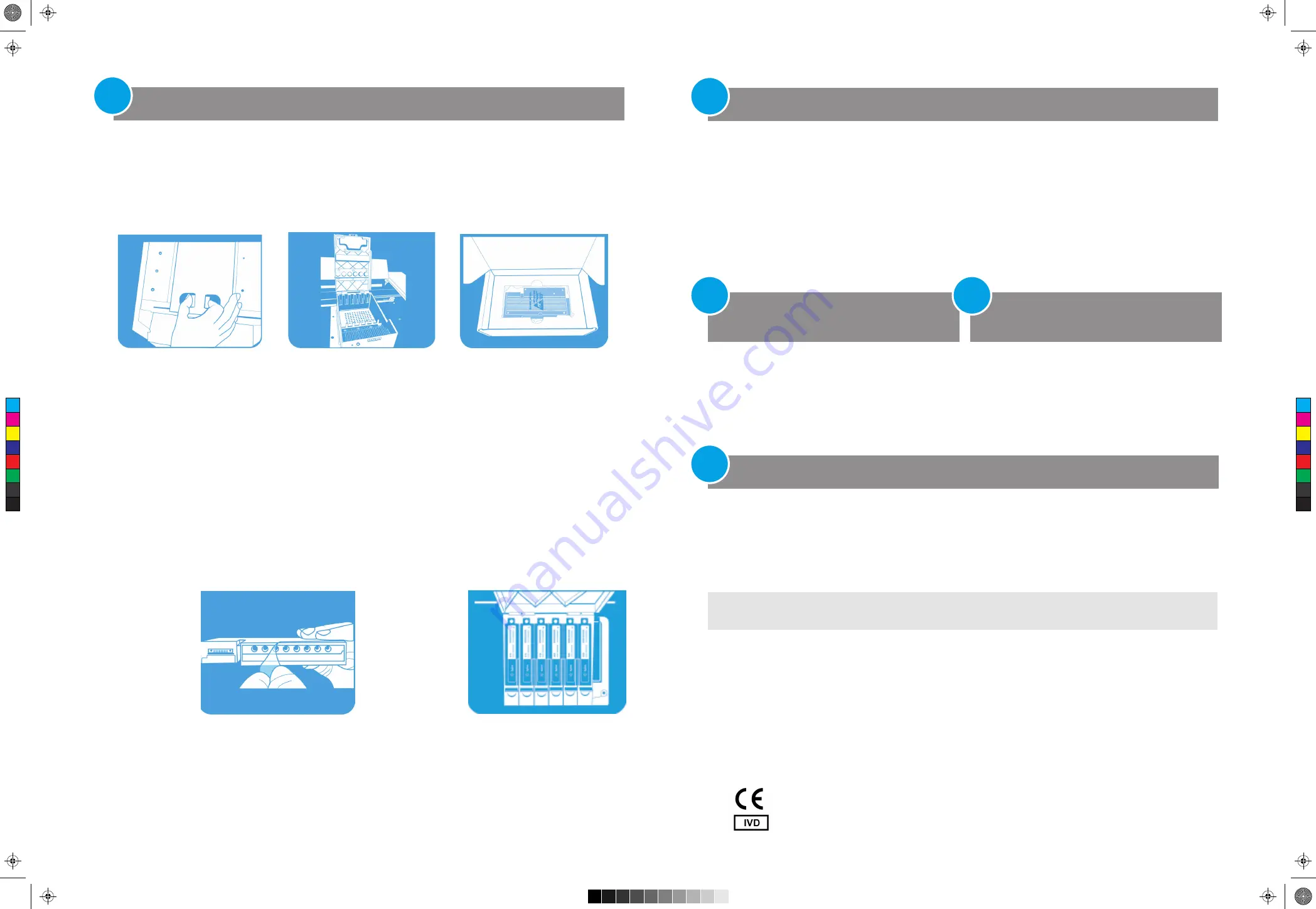
5) Open the boxes containing the optical modules. Remove the top piece of foam from each box (Figure 8) then remove
the plastic bag containing the optical module.
6)
Install the optical modules into the slots
.
a)
Open the plastic bag and remove the optical module.
b)
Peel
o
ff the plastic film from the edge of the optical mo
dule (see figure 9). Once the film is removed, do not
touch
the exposed ed
g
e.
c)
Put the optical module
into an available slot
. The correct orientation for the optical
module
is
label side up with the Agilent spark closer to the front of the instrument (see Figure 10).
NOTE: If you are installing fewer than six optical modules, make sure that the empty slots are on the
left
-most side
of the housing.
7)
Lower the lid on the optical module housing until it clicks shut. When you turn on the instrument for the first time, it
will
prompt you to calibrate the background for the optical modules.
Install the optical modules
(continued )
step
3
With the instrument door still open, clean the outside and inside surfaces of the thermal block.
1) Lift the lid of the thermal block by pulling forward on the handle of the lid and then lifting the lid up and away from
the
thermal block.
2) Using an aerosol can of compressed air, clean out the wells of the thermal block. Hold the can 3–4 inches away from
the thermal block as you press the trigger.
3) Moisten a lint-free cleansing tissue with dH
2
0, and gently wipe down the thermal block and the underside of the lid.
Then, close the lid of the thermal block and wipe down the top of the lid.
4) Close the instrument door.
Clean the thermal block
step
4
Connect the instrument to a network or directly to a PC
step
7
Figure 9
Removal
of plastic film from
optical module
Figure 10
Installed
optical modules
Figure 8
Optical module in its
shipping box
Figure 7
Slots for the optical
modules
C
M
Y
CM
MY
CY
CMY
K
AriaMx_Poster_18x12_2.6.pdf 2 1/15/15 8:56 AM
Open the lid on the optical module housing carrier. a) With your thumb and index finger, pinch together the two pieces
of plastic in the indentation on the top of the carrier (see Figure 6). b) Lift the lid all the way back to reveal the six slots
for the optical modules (see Figure 7).
4)
Figure 6
Opening of the optical
module housing