


2-28
Chapter 2
System Verification and Performance Tests
Agilent 8753ES System Verification and Performance Tests
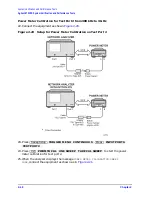
5. Minimum R Channel Level
This test confirms that phase lock can be achieved at a specified minimum R channel input
power. Power from the analyzer’s output port is fed into the R channel receiver using the
input found on the front panel. Observations are made for proper phase lock conditions.
Analyzer warm-up time: 30 minutes
Specifications
Required Equipment
Procedure
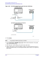
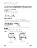
1. Connect the equipment as shown in
.
Figure 2-13
Minimum R Channel Level Test Setup
Frequency Range
Minimum R Channel
Level
300 kHz to 3 GHz
<
−
35 dBm
3 GHz to 6 GHz
a
a. Only for analyzers with Option 006.
<
−
30 dBm
Description
HP/Agilent Part or Model Number
Adapter: APC-3.5 (m) to APC-7
1250-1746
Cable: APC-7, 24-inch
8120-4779
Required Equipment for 75
Ω
Analyzers (Option 075)
Minimum Loss Pad: 50
Ω
to 75
Ω
11852B
Cable: 50
Ω
Type-N, 24-inch
8120-4781
Adapter: APC-3.5 (m) to Type-N (f)
1250-1750
Summary of Contents for 8753ES
Page 14: ...Contents xiv Contents ...
Page 15: ...1 1 1 Service Equipment and Analyzer Options ...
Page 26: ...1 12 Chapter1 Service Equipment and Analyzer Options Service and Support Options ...
Page 27: ...2 1 2 System Verification and Performance Tests ...
Page 203: ...3 1 3 Adjustments and Correction Constants ...
Page 262: ...3 60 Chapter3 Adjustments and Correction Constants Sequences for Mechanical Adjustments ...
Page 263: ...4 1 4 Start Troubleshooting Here ...
Page 297: ...5 1 5 Power Supply Troubleshooting ...
Page 317: ......
Page 318: ...6 1 6 Digital Control Troubleshooting ...
Page 337: ...6 20 Chapter6 Digital Control Troubleshooting GPIB Failures ...
Page 338: ...7 1 7 Source Troubleshooting ...
Page 369: ...7 32 Chapter7 Source Troubleshooting Source Group Troubleshooting Appendix ...
Page 370: ...8 1 8 Receiver Troubleshooting ...
Page 381: ...8 12 Chapter8 Receiver Troubleshooting Troubleshooting When One or More Inputs Look Good ...
Page 382: ...9 1 9 Accessories Troubleshooting ...
Page 389: ...9 8 Chapter9 Accessories Troubleshooting Inspect the Error Terms ...
Page 390: ...10 1 10 Service Key Menus and Error Messages ...
Page 439: ...10 50 Chapter10 Service Key Menus and Error Messages Error Messages ...
Page 440: ...11 1 11 Error Terms ...
Page 451: ...11 12 Chapter11 Error Terms Error Correction ...
Page 452: ...12 1 12 Theory of Operation ...
Page 482: ...13 1 13 Replaceable Parts ...
Page 487: ...13 6 Chapter13 Replaceable Parts Ordering Information Figure 13 1 Module Exchange Procedure ...
Page 500: ...Chapter 13 13 19 Replaceable Parts Replaceable Part Listings Figure 13 7 8753ET Cables Top ...
Page 502: ...Chapter 13 13 21 Replaceable Parts Replaceable Part Listings Figure 13 8 8753ES Cables Top ...
Page 512: ...Chapter 13 13 31 Replaceable Parts Replaceable Part Listings Figure 13 13 8753ES Cables Front ...
Page 544: ...14 1 14 Assembly Replacement and Post Repair Procedures ...
Page 550: ...Chapter 14 14 7 Assembly Replacement and Post Repair Procedures Covers Figure 14 2 Covers ...
Page 597: ...14 54 Chapter14 Assembly Replacement and Post Repair Procedures Post Repair Procedures ...


