


Chapter 7
7-13
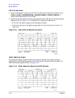
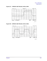
Source Troubleshooting
Phase Lock Error
4. Verify the remaining CW frequencies, comparing the counter reading with the value in
• Press
.
• Press .
5. Press
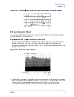
to count the frequency of the 2nd LO signal.
6. Press
. Verify that the counter reading matches the
corresponding 2nd LO value for the CW frequency. (Refer to
.)
7. Verify the remaining CW frequencies, comparing the counter reading with the value in
• Press
.
• Press .
8. Press
to count the frequency of the PLREF signal.
9. Press
. Verify that the counter reading matches the
corresponding PLREF value for the CW frequency. (Refer to
10.Verify the remaining CW frequencies, comparing the counter reading with the value in
• Press
.
• Press .
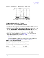
11.Check the results.
• If all the counter readings match the frequencies listed in
, skip ahead to
“A13/A14 Fractional-N Check” on page 7-20
.
• If the counter readings are incorrect at the 500 kHz and 2 MHz settings only, go to
“FN LO at A12 Check” on page 7-16
• If all the counter readings are incorrect at all three CW frequencies, the counter may
be faulty. Perform the
check of the signals described next. (If
the signals are good, either the A10 or A14 assemblies could be faulty.)
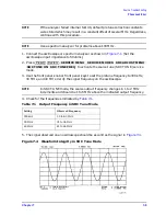
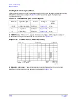
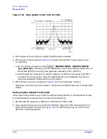
Table 7-2
Analog Bus Check of Reference Frequencies
CW Frequency
Analog Bus Node 21
100 kHz
Analog Bus Node 24
2nd LO
Analog Bus Node 25
PLREF
500 kHz
0.100 MHz
0.504 MHz
0.500 MHz
2 MHz
0.100 MHz
2.007 MHz
2.000 MHz
50 MHz
0.100 MHz
0.996 MHz
1.000 MHz
NOTE: The counter should indicate the frequencies listed in this table to within
±
0.1%.
Accuracy may vary with gate time and signal strength.
2
M/
µ
50
M/
µ
24
x1
Menu
CW FREQ
500
k/m
2
M/
µ
50
M/
µ
25
x1
Menu
CW FREQ
500
k/m
2
M/
µ
50
M/
µ
Summary of Contents for 8753ES
Page 14: ...Contents xiv Contents ...
Page 15: ...1 1 1 Service Equipment and Analyzer Options ...
Page 26: ...1 12 Chapter1 Service Equipment and Analyzer Options Service and Support Options ...
Page 27: ...2 1 2 System Verification and Performance Tests ...
Page 203: ...3 1 3 Adjustments and Correction Constants ...
Page 262: ...3 60 Chapter3 Adjustments and Correction Constants Sequences for Mechanical Adjustments ...
Page 263: ...4 1 4 Start Troubleshooting Here ...
Page 297: ...5 1 5 Power Supply Troubleshooting ...
Page 317: ......
Page 318: ...6 1 6 Digital Control Troubleshooting ...
Page 337: ...6 20 Chapter6 Digital Control Troubleshooting GPIB Failures ...
Page 338: ...7 1 7 Source Troubleshooting ...
Page 369: ...7 32 Chapter7 Source Troubleshooting Source Group Troubleshooting Appendix ...
Page 370: ...8 1 8 Receiver Troubleshooting ...
Page 381: ...8 12 Chapter8 Receiver Troubleshooting Troubleshooting When One or More Inputs Look Good ...
Page 382: ...9 1 9 Accessories Troubleshooting ...
Page 389: ...9 8 Chapter9 Accessories Troubleshooting Inspect the Error Terms ...
Page 390: ...10 1 10 Service Key Menus and Error Messages ...
Page 439: ...10 50 Chapter10 Service Key Menus and Error Messages Error Messages ...
Page 440: ...11 1 11 Error Terms ...
Page 451: ...11 12 Chapter11 Error Terms Error Correction ...
Page 452: ...12 1 12 Theory of Operation ...
Page 482: ...13 1 13 Replaceable Parts ...
Page 487: ...13 6 Chapter13 Replaceable Parts Ordering Information Figure 13 1 Module Exchange Procedure ...
Page 500: ...Chapter 13 13 19 Replaceable Parts Replaceable Part Listings Figure 13 7 8753ET Cables Top ...
Page 502: ...Chapter 13 13 21 Replaceable Parts Replaceable Part Listings Figure 13 8 8753ES Cables Top ...
Page 512: ...Chapter 13 13 31 Replaceable Parts Replaceable Part Listings Figure 13 13 8753ES Cables Front ...
Page 544: ...14 1 14 Assembly Replacement and Post Repair Procedures ...
Page 550: ...Chapter 14 14 7 Assembly Replacement and Post Repair Procedures Covers Figure 14 2 Covers ...
Page 597: ...14 54 Chapter14 Assembly Replacement and Post Repair Procedures Post Repair Procedures ...


