background image

20

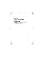
Save a Block of Data

Define a block of data within the current editor user pattern 
memory, then save the block to any pattern store large 
enough to hold the pattern. The current pattern store 
contents are overwritten by the new data being saved.

Select , 


or 

 or 

 - set cursor on first bit of 

block to be saved - select 

 - set cursor on 

last bit of block (block shown underlined) - select 

 or 

 or 

 store.

Generate an Alternate Pattern

Select , 


or 

, , 

use numeric keypad, then press 

. You can load a 

prbs or user pattern into each half of the alternate pattern 
(use load block function).

Control Alternate Pattern Switching

You can control alternate patterns from the front panel 
AUXILIARY INPUT port or over HP-IB.

Select 

 - select an alternate pattern 

 or 

, set 

 to 

 for control via the 

AUXILIARY INPUT, and 

 for front panel control.

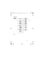
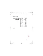
pattern

edit ram user

edit disk user

INTERNL PATT

DISK PATT

savedel block

save to ram

save to disk

INTERNL PATT

DISK PATT

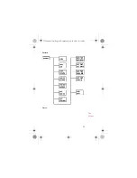
pattern

edit ram user

edit disk user

CURRENT PATT

ALTPAT ON

YES SET PAT LENGTH

ENTER

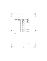
pattern

ram user pattern

disk user pattern

ALT PAT AUX USR

AUX

USR

Pat Editor 
Operation

71612-90017.fm  Page 20  Wednesday, July 18, 2001  11:26 AM

Summary of Contents for 71612

Page 1: ...ront and Rear Panel Cabling 9 Initial Switch on Initial Switch on 11 Pat Gen Setup Pattern Generator Setup 12 Error Det Setup Error Detector Setup 14 Meas Gating Measurement Gating 16 Measurements Measurements 17 Pat Editor Operation Pattern Editor Operation 19 Disk Operation Disk Operation 21 General Functions General Functions 22 The Menus The Menus 23 BER What is it BER Basics 43 BERT Decision ...

Page 2: ...are dc coupled DO NOT APPLY ANY EXTERNAL VOLTAGE TO THESE OUTPUTS This will damage the internal amplifiers Take particular care when using a bias tee to connect it the correct way Intro to the 71612 71612 90017 fm Page 3 Wednesday July 18 2001 11 26 AM ...

Page 3: ...4 Intro to the 71612 71612 90017 fm Page 4 Wednesday July 18 2001 11 26 AM ...

Page 4: ...5 Agilent 71612 12 5 Gb s Error Performance Analyzer Intro to the 71612 71612 90017 fm Page 5 Wednesday July 18 2001 11 26 AM ...

Page 5: ...ment results Instrument Hardkeys gain instant access to primary instrument functions such as data output or result pages The keys are color coded to indicate their function Green for configuration keys Blue for result pages Black for immediate selection keys for gating and audio instrument hardkeys Intro to the 71612 71612 90017 fm Page 6 Wednesday July 18 2001 11 26 AM ...

Page 6: ... with which they are associated They are Blue softkeys window assigned to Results Page occupies two thirds of screen Green softkeys window assigned to pattern generator error detector configuration Yellow softkeys green yellow window assigned to Pattern Editor Grey softkeys window assigned to user pattern selection and save Softkeys that are greyed out are not valid for the currently selected inst...

Page 7: ...ng Both methods enable menus of softkeys that give access to all instrument functions Parameter Control Keys Display knob Use the display RPG knob to change parameters and select operating values Numeric keypad Use the numeric keypad to enter numeric values Use the two step keys to change parameters up or down DISPLAY MENU Intro to the 71612 71612 90017 fm Page 8 Wednesday July 18 2001 11 26 AM ...

Page 8: ...9 Front and Rear Panel Cabling System Back to Back Connection Front Rear Cabling 71612 90017 fm Page 9 Wednesday July 18 2001 11 26 AM ...

Page 9: ...10 HP MSIB Cabling rear panel Front Rear Cabling 71612 90017 fm Page 10 Wednesday July 18 2001 11 26 AM ...

Page 10: ... your system and check that all LEDs light up then go off after a few seconds The green ACT LED on the 70843 will be lit up when the instrument owns the keyboard and display 4 A lit up red E at the top left of the screen indicates an error in any instrument on row 0 of the address map Refer to the 70004A Display Operation Manual for information about the address map The red E also blinks if the di...

Page 11: ... select data output parameters The DATA and DATA OUT ports can be set to be independent or track together Set Up Subrate Outputs Select then use the available softkeys to setup clock data parameters Add Errors Select then either or clock output SIG GEN FREQ FREQ STEP SIG GEN AMPLTD SIG GEN ON OFF C TRCK ON OFF C TRCK ON OFF data output D TRCK ON OFF D TRCK ON OFF subrate outputs error add ERR ADD ...

Page 12: ...er alternates with the pattern and for all other patterns the trigger pulse occurs at lowest common multiple of 256 and pattern length Select a pattern trigger as follows For a pure PRBS select enter PRBS code word using numeric keypad For alternate patterns select Trigger pulse is at bit 0 of pattern or alternates with pattern A B changeover For all other patterns select then select pattern bit n...

Page 13: ...lts Control Synchronization and Audible Tone Select and use the softkeys to control Error Detector synchronization and the audible tone that sounds when errors occur Synchronization to the incoming pattern can be performed automatically or manually In manual forces the Error Detector to attempt synchronization with the received pattern Synchronization is gained when the measured error rate is less...

Page 14: ...lect Error Detector Trigger Output Pulse Select then set softkey to or Provides pattern and clock trigger Clock Trigger a square wave at 1 8 of clock rate Pattern Trigger for a pure PRBS it is 1 pulse per 32 pattern repetitions For all other patterns pulse occurs at lowest common multiple of 256 and pattern length trigger setup ERR O P RZ 200ns trigger setup ED TRIG PAT CLK PAT CLK Error Det Setup...

Page 15: ...measurement period Select a Measurement Period Select then or Gate by Time Bits or Errors Select or then or then If you select use the numeric keypad then softkeys to select gating period RUN GATING STOP GATING MENU gating RUN GATING STOP GATING gating MANUAL SINGLE REPEAT SINGLE REPEAT GATE BY TIME GATE BY ERRS GATE BY BITS GATING PERIOD GATE BY TIME Meas Gating 71612 90017 fm Page 16 Wednesday J...

Page 16: ... bit specified is known as the BER location There are three measurements Bit BER Block BER and Error Location Capture Bit BER Select use numeric keypad or display knob to select BIT ERR ADDRESS Press at end of measurement period select to view Bit BER results RUN GATING STOP GATING input eye 0 1 THR AUTOMAN EYE EDG THRSHLD CLK DAT ALIGN result pages EYE RESULTS input eye 0 1 THR AUTOMAN EYE EDG TH...

Page 17: ... measurement period Error Location Capture Select view the error location in the Error Location Config window Note the softkey is greyed out if BLOCK BER is currently selected error location BLOCK BER BLOCK START BLOCK LENGTH RUN GATING result pages MAIN RESULTS error location CAPTURE ERROR CAPTURE ERROR Measure ments 71612 90017 fm Page 18 Wednesday July 18 2001 11 26 AM ...

Page 18: ... to fit between cursor and pattern end determines whether bits are inserted or replaced Select or or set screen cursor to bit position where data block is to be loaded Set mode select a or pattern prbs zero sub mark density user pattern pattern edit ram user edit disk user INTERNL PATT DISK PATT toggle screen save pattern INTERNL PATT DISK PATT INSERT REPLACE pattern edit ram user edit disk user I...

Page 19: ... prbs or user pattern into each half of the alternate pattern use load block function Control Alternate Pattern Switching You can control alternate patterns from the front panel AUXILIARY INPUT port or over HP IB Select select an alternate pattern or set to for control via the AUXILIARY INPUT and for front panel control pattern edit ram user edit disk user INTERNL PATT DISK PATT savedel block save...

Page 20: ...k Select Delete a Disk Pattern Store Select then select the store to be deleted pattern disk utils format disk FORMAT YES pattern disk utils delete diskpat DISK PATT Disk Operation 71612 90017 fm Page 21 Wednesday July 18 2001 11 26 AM ...

Page 21: ...call Instrument setups Select then or Build Your Own Display of Results Status Items Select use the softkeys displayed to add delete items from the user s page Press to delete all items from the user s page MENU misc trigger setup recall setup save setup result pages USER S PAGE build usr pge CLEAR USR PGE General Functions 71612 90017 fm Page 22 Wednesday July 18 2001 11 26 AM ...

Page 22: ...l major instrument functions The following menu maps illustrate the softkey choices for each function or group of functions The boxes shown on the charts represent actual key presses and illustrate the sequence of key presses required to perform individual functions MENU The Menus 71612 90017 fm Page 23 Wednesday July 18 2001 11 26 AM ...

Page 23: ...24 Main Menu Notes The Menus 71612 90017 fm Page 24 Wednesday July 18 2001 11 26 AM ...

Page 24: ...25 Pattern Notes The Menus 71612 90017 fm Page 25 Wednesday July 18 2001 11 26 AM ...

Page 25: ...26 Pattern PRBS Notes The Menus 71612 90017 fm Page 26 Wednesday July 18 2001 11 26 AM ...

Page 26: ...27 Pattern Zerosub Notes The Menus 71612 90017 fm Page 27 Wednesday July 18 2001 11 26 AM ...

Page 27: ...28 Pattern Markdensity Notes The Menus 71612 90017 fm Page 28 Wednesday July 18 2001 11 26 AM ...

Page 28: ...29 Pattern Ram User Notes The Menus 71612 90017 fm Page 29 Wednesday July 18 2001 11 26 AM ...

Page 29: ...30 Pattern Disk User Pattern Notes The Menus 71612 90017 fm Page 30 Wednesday July 18 2001 11 26 AM ...

Page 30: ...31 Pattern Edit Ram User Notes The Menus 71612 90017 fm Page 31 Wednesday July 18 2001 11 26 AM ...

Page 31: ...32 Pattern Edit Disk User Notes The Menus 71612 90017 fm Page 32 Wednesday July 18 2001 11 26 AM ...

Page 32: ...33 Pattern Edit User Notes The Menus 71612 90017 fm Page 33 Wednesday July 18 2001 11 26 AM ...

Page 33: ...34 Data Output Notes The Menus 71612 90017 fm Page 34 Wednesday July 18 2001 11 26 AM ...

Page 34: ...35 Clock Output Notes The Menus 71612 90017 fm Page 35 Wednesday July 18 2001 11 26 AM ...

Page 35: ...36 Error Add Notes The Menus 71612 90017 fm Page 36 Wednesday July 18 2001 11 26 AM ...

Page 36: ...37 Trigger Setup The Menus 71612 90017 fm Page 37 Wednesday July 18 2001 11 26 AM ...

Page 37: ...38 Result Pages Notes The Menus 71612 90017 fm Page 38 Wednesday July 18 2001 11 26 AM ...

Page 38: ...39 Input Eye Notes The Menus 71612 90017 fm Page 39 Wednesday July 18 2001 11 26 AM ...

Page 39: ...40 Sync Audio Notes The Menus 71612 90017 fm Page 40 Wednesday July 18 2001 11 26 AM ...

Page 40: ...41 Gating Notes The Menus 71612 90017 fm Page 41 Wednesday July 18 2001 11 26 AM ...

Page 41: ...42 Error Location Notes The Menus 71612 90017 fm Page 42 Wednesday July 18 2001 11 26 AM ...

Page 42: ...s and also measure error ratio Often the two components are used together but not always a PG makes an ideal stimulus for component design work In some BERTs the clock source may also be separate A BERT makes physical layer measurements and differs from a protocol or SONET tester in the following ways A BERT can usually Vary voltage levels Vary the timing relationship between clock and data Vary t...

Page 43: ...44 BER What is it 71612 90017 fm Page 44 Wednesday July 18 2001 11 26 AM ...

Page 44: ...ting the position of this decision point correct This means getting both the vertical decision threshold voltage and the horizontal clock data delay correctly set The clock data delay must be adjusted so that the decision point is positioned at the center of the bit period Threshold too high some ones counted as zeros Threshold too low some zeros counted as ones Threshold about right Probability o...

Page 45: ...n to reference pattern yield an error ratio of 2x10 3 Only one position gives error free operation However the error ratio in the other positions could easily be better than the synchronization threshold set and thus the error detector will say it has achieved satisfactory operation Look for this when there is a stable error ratio which cannot be explained in any other way Change the sync threshol...

Page 46: ...e of confidence 0 95 95 confidence n number of bits examined with no error detected b desired residual BER BER Approx Test Time for 95 Confidence Level STM 256 OC 768 STM 64 OC 192 STM 16c OC 48c STM 4c OC 12c STM 1 OC 3 1x10 20 240 year 960 year 3 8k year 15 2k year 61k year 1x10 16 8 7 day 35 day 139 day 1 5 year 6 1 year 1x10 15 21 hr 3 5 day 14 day 56 day 224 day 1x10 14 2 1 hr 8 4 hr 1 4 day ...

Page 47: ...fiers dominates receiver noise Q factor is usually measured using either network equipment receiver electronics or a BERT in each case using the ability to vary the decision threshold The BER is recorded versus decision level down the centre of the eye As the decision threshold is moved towards the 1 and 0 levels the BER becomes dominated by the noise on those levels The data may be divided into t...

Page 48: ...ss accurate oscilloscopes do not sample every bit transmitted and the measurement can become dominated by the front end electronics of the instrument rather than the system under test Q is defined as where I1 mean level of a 1 I0 mean level of a 0 δ1 standard deviation of a 1 δ0 standard deviation of a 0 Approximate form of BER expression is reasonably accurate for Q 3 and is therefore appropriate...

Page 49: ...diagram and can show degradations such as noise and inter symbol interference when used with appropriate test patterns They also allow observation of low probability impairments and a visible indication of sampling point margin Plot produced by E4543A application software BER What is it 71612 90017 fm Page 50 Wednesday July 18 2001 11 26 AM ...

Page 50: ...51 BERT Troubleshooting Setting up a Simple BER Measurement Pattern Generator setup Error Detector setup BER What is it 71612 90017 fm Page 51 Wednesday July 18 2001 11 26 AM ...

Page 51: ...52 BERT Connected Back to Back BER What is it 71612 90017 fm Page 52 Wednesday July 18 2001 11 26 AM ...

Page 52: ...53 BERT Connected to DUT BER What is it 71612 90017 fm Page 53 Wednesday July 18 2001 11 26 AM ...

Page 53: ...ource Decimation Allows results to be compared against theory PRBSs Pseudo Random Bit or Binary Sequences are an accepted way of testing digital circuits in many industries from radar tape drives and hard disks to satellite communication and fiber optics In all of these the quality of a system is based on its ability to pass data error free PRBSs provide a means to simulate the type of traffic tha...

Page 54: ...series of N shift registers connected together The output and one or more other points are XOR ed together and fed back to the input Any random seed will go to a known state unless all zeros are present this will stay as all zeros forever The tap point R is standardized for common sequences The commonly used PRBSs have combinations of R and N that cause them to be maximal length not all combinatio...

Page 55: ...ver appears as it would lock up the shift registers hence 2n 1 2n 1 will contain a maximum run of n ones n 1 zeros Does not repeat for maximal length sequences ITU Standard n Sequence length bits Longest run of ones Longestrun of zeros 7 127 7 6 10 1023 10 9 11 2047 11 10 15 32 767 15 14 20 1 048 575 20 19 23 8 388 607 23 22 31 2 147 483 647 31 30 BER What is it 71612 90017 fm Page 56 Wednesday Ju...

Page 56: ...he closer to a continuous spectrum produced the more like an analog noise source the test signal looks The benefit of this is that such a stimulus will show up any frequency dependent effects in a device under test For example a clock recovery circuit designed to lock onto a single frequency may have a tendency to lock onto harmonics A long PRBS may uncover such undesirable behavior BER What is it...

Page 57: ...With decimation of a PRBS if every 2n bits of a PRBS is selected the result is the same PRBS data but each sequence is phase shifted by 2n 1 2n bits from the others that is sequence length decimation factor For example decimate a 24 1 sequence by 2 Original 24 1 010110010001111010110010001111 Odd bits 0 0 1 0 0 0 1 1 1 1 0 1 0 1 1 Even bits 1 1 0 1 0 1 1 0 0 1 0 0 0 1 1 Sequence length decimation ...

Page 58: ... 75 V 3 25 V Vpp 900 mV 850 mV 850 mV Termination 0 V 2 V 3 V Z 50 Ω 50 Ω 50 Ω Supply 0 3 5 V 0 5 2 V 5 0 V Family LVPECL TTL LVTTL Vhi 2 4 V 2 4 V 2 0 V Vlo 1 55 V 0 8 V 0 8 V Vpp 850 mV Termination 1 3 V Z 50 Ω Supply 3 3 0 V 5 0 V 3 3 0 V BER What is it 71612 90017 fm Page 59 Wednesday July 18 2001 11 26 AM ...

Page 59: ...60 Terminations BER What is it 71612 90017 fm Page 60 Wednesday July 18 2001 11 26 AM ...

Page 60: ...61 BER What is it 71612 90017 fm Page 61 Wednesday July 18 2001 11 26 AM ...

Page 61: ...C 48 STM 16 2 48832 Gb s OC 192 STM 64 9 95328 Gb s OC 768 STM 256 39 81312 Gb s Selected Enterprise Rates Name Rate Ethernet with coding 12 5 Mb s Fast Ethernet 125 Mb s Gigabit Ethernet 1 25 Gb s 2 x Gigabit Ethernet 2 5 Gb s 10 x Gigabit Ethernet 9 95 Gb s or 12 5 Gb s or 4 channels at 3 125 Gb s Fiber Channel 1 063 Gb s 2 x Fiber Channel 2 12 Gb s BER What is it 71612 90017 fm Page 62 Wednesda...

Reviews: