


User Connections and Considerations
39
4
User Connections and Considerations
Rear Panel Connections
Shock Hazard
Disconnect ac power before making rear panel connections.
Application connections are made to the output terminals and analog connector. The connections are the same for Series
654xA and 655xA supplies and similar for the Series 657xA supplies. Unless otherwise specified, instructions in this
chapter apply to all models.
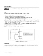
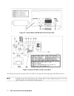
Output Connectors
The + and - load connections are made at the rear panel. Depending on the model (see Figure 4-1 or Figure 4-2), either
terminals or screw-down bus bars (+ and -) connect the load to the power supply. The general procedure is as follows:
1.
Remove the output safety cover.
2.
Connect the load wires.
3.
Replace the output safety cover.
For more specific information, refer to the following applicable paragraph.
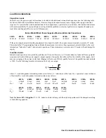
Series 654xA and 655xA Supplies
•
On Series 654xA:
•
strip the end of each load wire and secure it to the appropriate terminal, using the screw provided on the terminal.
•
On Series 655xA:
•
strip the end of each load wire and fasten a suitable terminal lug to the end.
•
using the screws provided on the output bus bars, attach the wire terminal lugs to the bus bars.
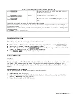
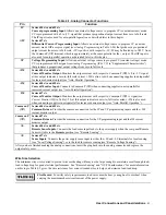
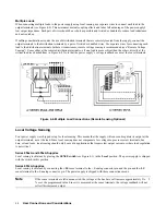
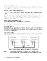
Series 657xA Supplies
•
strip the end of each load wire and fasten a suitable terminal lug to the end.
•
make a suitable opening in the output safety cover by removing one or more cover knockouts (see Figure 4-2).
Do not leave uncovered holes in the safety cover. If too many knockouts have been removed, install a
new cover (see Table 1-3).
•
feed the wires through the safety cover.
•
using the screws provided on the output bus bars, attach the wire terminal lugs to the bus bars.
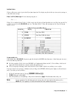
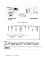
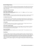
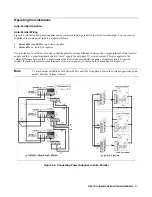
Analog Connector
The rear panel has a 7-pin analog connector with quick-disconnect plug (see Figure 4-3) for making the following optional
connections:
•
remote sense leads
•
an external current monitor
•
an external programming voltage source
•
connecting two or more power supplies in auto-parallel


