


2-34
Agilent 4155C/4156C User’s Guide Vol.1, Edition 11
Installation
Mounting Connectors
Installing the interlock circuit
Install the interlock circuit as follows:
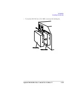
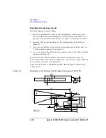
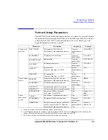
1. Mount two mechanical switches on your shielding box, so that the switches
close when the door of the shielding box is closed, and open when the door is
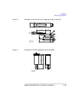
opened. For the dimensions of the switch, see Figure 2-3 and Figure 2-4 below.
2. Mount an LED on your shielding box. For the dimensions of the LED, see
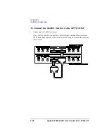
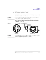
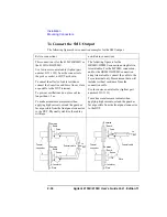
3. Use wire to connect the two switches in series between pin number 1 and 2 (or
3) of the interlock connector. See Figure 2-2.
4. Use wire to connect the LED between pin number 4 and 5 (or 6) of the interlock
connector. See Figure 2-2.
If the 4155C/4156C Intlk connector is connected to the interlock circuit, the
4155C/4156C SMU
cannot
force more than ±40 V when the door is open. When the
door is closed, it can force more than ±40 V.
When more than ±40 V is forced from an SMU, the LED lights to indicate
high
voltage output
.
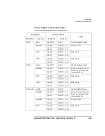
Figure 2-3
Dimensions of the Interlock Switch (Agilent part number 3101-0302)
3.1
Switc
h on
59.4
8.1
10
UGI01011,85x60
Units: mm
NC
NO
COM
6.35
22.2
27.8
37.8
2.8
6.
5
5.
5
15
.9
18
.8
4.
7
5
10
.3
4.
3
2.
8
2.
8
Switch of
f
Ma
x 9
15.
2
10
.3
2.
8
3.1
Summary of Contents for 41501A
Page 19: ...Contents Agilent 4155C 4156C User s Guide Vol 1 Edition 11 9 Accessories and Options...
Page 20: ...Agilent 4155C 4156C User s Guide Vol 1 Edition 11 Contents...
Page 21: ...1 Introducing the 4155C 4156C...
Page 41: ...2 Installation...
Page 84: ...2 44 Agilent 4155C 4156C User s Guide Vol 1 Edition 11 Installation Maintenance...
Page 85: ...3 Connecting to Network...
Page 129: ...4 File Operations...
Page 152: ...4 24 Agilent 4155C 4156C User s Guide Vol 1 Edition 11 File Operations Backing Up a Diskette...
Page 153: ...5 Print Plot Function...
Page 198: ...5 46 Agilent 4155C 4156C User s Guide Vol 1 Edition 11 Print Plot Function Output Examples...
Page 199: ...6 External Keyboard...
Page 203: ...7 Initial Settings...
Page 209: ...8 Specifications...
Page 243: ...9 Accessories and Options...


