


12
Agilent 16441A User’s Guide, Edition 4
User's Guide
Installation
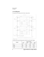
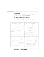
Connecting the R-Box to the 4155/4156
Before connecting the R-box to the 4155/4156 and 41501, turn off the instruments.
1. Connect the To R-Box terminal on the 4155/4156 rear panel to the Control
terminal on the R-Box rear panel using a 3.0 m or 1.5 m control cable.
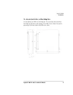
2. Connect the instrument measurement terminals to the R-Box input terminals as
shown below:
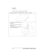
3. Connect the R-Box output terminals to the input terminals of the 16442A test
fixture or an connector plate using 40 cm triaxial cables as shown below:
When you use the connector plate, use a low-noise coaxial cable (Agilent part
number: 8120-3674) from the connector plate to DUT. If you use insufficiently
insulated cables, leakage current may occur.
Instrument
terminals
R-Box Input
Cable
4155 MPSMU
Input Force
3 m or 1.5 m Triaxial Cable
4156 HRSMU
Input
(Force/Sense)
3 m or 1.5 m Kelvin Triaxial Cable
41501 MPSMU
Input Force
3 m or 1.5 m Triaxial Cable
41501 HPSMU
Input
(Force/Sense)
3 m or 1.5 m Kelvin Triaxial Cable
R-Box Output
16442A Input or Connector Plate Input
Output Force
a
a. For non-Kelvin connection.
SMU1, 2, 3, 4, 5, or 6
Output Force
b
b. For the Kelvin connection, two triaxial cables must be used to con-
nect the R-Box and the 16442A, instead of a Kelvin triaxial cable.
SMU1
SMU3
SMU5
Output Sense
b
SMU2
SMU4
SMU6


