


SECTION 00 -- GENERAL INFORMATION
8
327 258 010
-- 01 -- 2008
Cab identification -- Fig. 6
The plate is located in the left lower side of the oper-
ator’s seat, under the concave opening control levers.
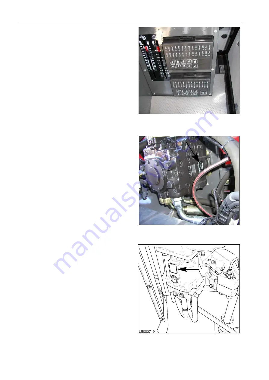
Hydrostatic pump identification
Fig. 7
The plate is located on the pump body front part
.
Hydrostatic motor identification
Fig. 8
The plate is located on the hydrostatic motor body
lower part.
6
7
8


