background image


31

 / 

31


  Warranty Information 


This product has been manufactured under the highest standards of quality and 
workmanship. We warrant to the original consumer purchaser that all aspects of 
this product will be free of defects in material and workmanship for one year from 
the date of purchase. A replacement for any defective part will be supplied free of 
charge for installation by the consumer. Defects or damage caused by the use of 
other than genuine parts are not covered by this warranty. This warranty shall be 
effective from the date of purchase as shown in the purchaser receipt.  
 
This warranty is valid for the original consumer purchaser only and excludes 
industrial, commercial or business use of the product, product damage due to 
shipment or failure which results from alteration, product abuse, or product 
misuse, whether performed by a contractor, service company, or consumer. We 
will not be responsible for labor charges and/or damage incurred in installation, 
repair or replacement nor for incidental or consequential damage.


For replacement parts, please call 1-866-370-2131 Monday 

– Friday 9AM–5PM Eastern Time 


General Customer Service: (888) 922-2336 7:00 am to 12:00 am CST (daily) 

Live Chat at: www.academy.com 

Email: [email protected] 

                       Please keep this instruction manual for future reference


SP-33-SW-095S-ADMY-20001


Summary of Contents for 164178

Page 1: ...l for future reference For replacement parts please call 1 866 370 2131 Monday Friday 9 00 AM 5 00 PM Eastern Time General Customer Service 888 922 2336 7 00 am to 12 00 am CST daily Live Chat at www academy com Email customerservice academy com Please keep this instruction manual for future reference ...

Page 2: ... Playground Safety Handbook recommend to install and maintain the playground equipment over at least 9 inches of wood chips mulch or shredded rubber for equipment up to 8 feet high or sand or pea gravel for equipment no more than 5 feet high as shock absorbing material Dirt and grass which are the most prevalent surfaces under home playground equipment do not adequately protect children from serio...

Page 3: ...ardware List 10 11 Assembly and Installation Instructions 12 30 Warranty Information 31 Note Before beginning assembly of product make sure all parts are present Compare parts with package content list and hardware contents If any part is missing or damaged do not attempt to assemble the unit Contact customer service for replacement parts ...

Page 4: ... Adult supervision is required during the use of this equipment at all times Unpack all parts Take a complete inventory of all parts and hardware using the parts and hardware lists in the following pages If any parts are missing do not return to the store Please call customer service toll free number listed on the cover page for assistance Store the product back in the original box and do not begi...

Page 5: ...er to the CONSUMER PRODUCT SAFETY COMMISSION S OUTDOOR HOME PLAYGROUND SAFETY HANDBOOK for detailed guidelines to prevent injuries from falls and other hazards on public and home playgrounds WARNINGS ON ANCHORING This product must be anchored be anchored into the ground to prevent movement and to make the product more stable during use There are different types and different methods of anchoring t...

Page 6: ...event damage or injuries On site adult supervision for children of all ages is required during use INSPECTION PRIOR TO EACH USE OR DAILY INSPECTION DO NOT use the equipment if any bolts or nuts are missing or loose ALWAYS check to ensure the equipment and all parts are well secured and stable before each use ALWAYS clear the play area of any rocks sharp objects or any materials that could be poten...

Page 7: ... when the temperature drops below 32 degrees F 0 degrees C remove and store the plastic slides indoors Owners shall be responsible for maintaining the legibility of the warning labels DISPOSAL INSTRUCTIONS Please use care when disassembling the equipment when it is no longer in operational condition Wear heavy duty working gloves to avoid injuries Fully disassemble the entire play set before dispo...

Page 8: ...8 31 Complete Product View ...

Page 9: ...rench Included W Big Allen Wrench Included Z Wrench Included V Special Socket Wrench Included X Medium Allen Wrench Included Tape Measure Not Included Hammer Not included Flat Head and Phillips Head Screwdriver Not included ...

Page 10: ...Frame tube 28 54 4 6 Frame tube 21 65 2 7 Connect Tube 1 8 Slide Platform Support 2 9 Slide Platform Connect Tube 2 10 Slide Top Support Bar 1 11 Slide handle bar Left 1 12 Slide handle bar Right 1 13 Bracket 2 14 Wood Plank 11 15 Wood Plank with Groove 1 16 Wood Plank Platform Support 2 17 Slide 1 X5 N Slide Front Support 1 18 Rock Climber 19 19 Anchor 6 ...

Page 11: ...8 12 D BOLT M6 X 0 79 2 E BOLT M6 X 1 38 4 F BOLT M6 X 2 17 2 G BOLT M6 X 2 56 6 H BOLT M6 X 4 53 2 I SCREW 48 J M8 WASHER LARGE 87 K M6 WASHER SMALL 12 L M6 ARC WASHER 22 M M8 SPRING WASHER LARGE 34 N M6 SPRING WASHER SMALL 16 O M8 NYLON NUT 19 P M8 ACORN NUT LARGE 34 Q M6 ACORN NUT SMALL 16 Z9 BOLT 1 4 2 36 4 ...

Page 12: ...sing A J and O as shown below Repeat in the same manner to assemble six sets Part Qty Hardware Qty 2 30 PCS A 6 PCS J 12 PCS O 6 PCS NOTE For easier assembly do not tighten the bolts all the way initially to allow room for adjustment You must go back and fully tighten all bolts after the entire play set is assembled Helpful Hint Make sure the bolt is protruding outward X6 ...

Page 13: ...low Secure all tubes together with A J and O as shown in the enlarged diagram Repeat in the same manner to assemble three sets Part Qty Hardware Qty 1 12 PCS A 3 PCS J 6 PCS O 3 PCS Helpful Hint Part 2 from the previous step is sandwiched between the new Part 1 Be sure to keep them separated in a star formation ...

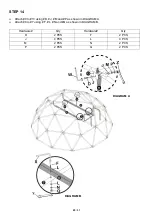
Page 14: ...cs of 1 to the previously assembled tubes 2 and 1 Secure using C J M and P in the order shown in the enlarged diagram Repeat in the same manner to assemble three sets Part Qty Hardware Qty 1 9PCS C 6 PCS J 12 PCS M 6 PCS P 6 PCS ...

Page 15: ...ure with C J M and P as shown in the enlarged diagram Part Qty Hardware Qty 1 9 PCS C 6 PCS J 12 PCS M 6 PCS P 6 PCS NOTE Adjust the tubing to make sure the dome is evenly shaped as a circle Helpful Hint Have one person hold the previously assembled sections upright while the other secures the bottom ...

Page 16: ...16 31 STEP 5 Attach two pcs of 1 to 2 and 1 using B J M and P as shown below Part Qty Hardware Qty 1 2 PCS B 1 PC J 2 PCS M 1 PC P 1 PC ...

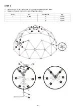
Page 17: ...17 31 STEP 6 Attach two pcs of 1 to 2 and 1 using A J and O as shown below Repeat in the same manner to connect the adjacent side Part Qty Hardware Qty 1 4 PCS A 2 PCS J 4 PCS O 2 PCS ...

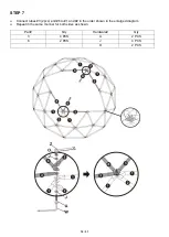
Page 18: ... 31 STEP 7 Connect tubes 3 2pcs and 6 to 1 and 2 in the order shown in the enlarged diagram Repeat in the same manner for both sides as shown Part Qty Hardware Qty 3 4 PCS A 2 PCS 6 2 PCS J 4 PCS O 2 PCS ...

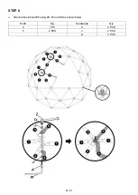
Page 19: ...19 31 STEP 8 Attach tubes 4 and 5 using A J and O as shown below Part Qty Hardware Qty 4 1 PC A 2 PCS 5 2 PCS J 4 PCS O 2 PCS ...

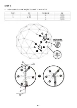
Page 20: ...20 31 STEP 9 Connect tubes 7 and 5 using A J and O as shown below Part Qty Hardware Qty 7 1 PC A 2 PCS 5 2 PCS J 4 PCS O 2 PCS ...

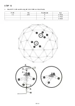
Page 21: ...21 31 STEP 10 Attach 13 to 5 and 6 using A J and O as shown below Part Qty Hardware Qty 13 2 PC A 2 PCS J 4 PCS O 2 PCS ...

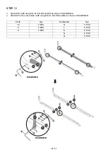
Page 22: ...o 8 using G L K N and Q as shown in DIAGRAM A Attach 9 to the outer sides of 8 using G L K N and Q as shown in DIAGRAM B Part Qty Hardware Qty 16 2 PCS G 6 PCS 8 2 PCS L 6 PCS 9 2 PCS K 6 PCS N 6 PCS Q 6 PCS DIAGRAM A DIAGRAM B ...

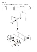
Page 23: ...23 31 STEP 12 Connect 10 in between 11 and 12 and secure together with 8 using E and L Part Qty Hardware Qty 10 1 PC E 2 PCS 11 1 PC L 2 PCS 12 1 PC ...

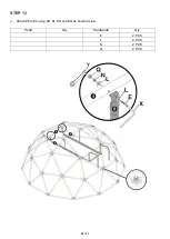
Page 24: ...24 31 STEP 13 Attach 8 to 4 using E L N and Q as shown below Part Qty Hardware Qty E 2 PCS L 4 PCS N 2 PCS Q 2 PCS ...

Page 25: ...ttach 9 to 13 using D J M and P as shown in DIAGRAM A Attach 8 to 7 using F L N and Q as shown in DIAGRAM B Hardware Qty Hardware Qty D 2 PCS F 2 PCS J 4 PCS L 4 PCS M 2 PCS N 2 PCS P 2 PCS Q 2 PCS DIAGRAM A DIAGRAM B ...

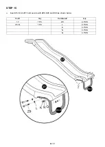
Page 26: ...26 31 STEP 15 Insert X5 N into 17 and secure with Z9 Z6 and Z4 as shown below Part Qty Hardware Qty 17 1 PC Z9 4 PCS X5 N 1 PC L 4 PCS K 4 PCS N 4 PCS Q 4 PCS ...

Page 27: ...27 31 STEP 16 Lift the slide onto the platform and secure both sides to 11 and 12 using H L K N and Q as shown below Part Qty Hardware Qty H 2 PCS L 2 PCS K 2 PCS N 2 PCS Q 2 PCS ...

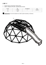
Page 28: ...sert 15 groove side into 17 Slide bottom Install in sequence 14 to 17 using I as shown below Part Qty Hardware Qty 14 11 PCS I 48 PCS 15 1 PS Helpful Hint It is recommended to use drill for easier assembly on this step ...

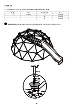
Page 29: ... 18 Attach 18 using J P and M to all tube connections shown below Part Qty Hardware Qty 18 19 PCS J 19 PCS M 19 PCS P 19 PCS Helpful Hint Use the special socket wrench provided to fully tighten the bolts and nuts ...

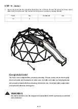
Page 30: ...y Hardware Qty 19 6 Congratulations You have now completed the product assembly Please make sure to thoroughly check all parts and hardware to make sure all bolts and nuts are fully tightened and properly installed before allowing children to use Constant adult supervision is required at all times during use WARNING Do not let children use the playground equipment until it is properly assembled an...

Page 31: ...e purchaser receipt This warranty is valid for the original consumer purchaser only and excludes industrial commercial or business use of the product product damage due to shipment or failure which results from alteration product abuse or product misuse whether performed by a contractor service company or consumer We will not be responsible for labor charges and or damage incurred in installation ...

Reviews: