background image

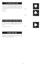
Turn the gas control knob to the minimum gas rate
position (    ) (Fig. 25), slightly depress the knob and
continue turning to the pilot position (   ) (Fig. 26). The fire
will go out and the pilot will remain lit and may be left on
permanently.

Turn off fan.

Turn the stove off as described. Depress the control
knob, turn to the off position (

) (Fig. 27) and the pilot will

go out.

Ensure fan is switched off.

Should the stove be subject to a power cut. On
restoration of the power the gas control will require
resetting manually (see page 15).

17

TO TURN STOVE OFF

TO TURN STOVE AND PILOT OFF

FIG 25.

FIG 26.

FIG 27.

POWER FAILURE

Summary of Contents for Coalbrookdale Little Wenlock Gas Power Flue

Page 1: ...WARNING This information is a copy of an original archive therefore Aga cannot be held responsible for its continued accuracy ...

Page 2: ...ealth and safety see below for information Firebricks Fuel beds Artificial Fuels when handling use disposable gloves Fire cement when handling use disposable gloves Glues and Sealants exercise caution if these are still in liquid form use face mask and disposable gloves Glass Yarn Mineral Wool Insulation Pads Ceramic Fibre Kerosene Gas Oil may be harmful if inhaled May be irritating to skin eyes n...

Page 3: ... 5 5kW NAT GAS PROPANE 3 96 kW 3 30 kW 2 20 kW 35 5 mbar PROPANE Cat 92 180 LPG 9206 2 3 mm PIEZO SPARK GENERATOR 4 62 kW 3 30 kW 2 31 kW 18 mbar NAT Cat 82 360 NAT NG 9008 2 3 mm PIEZO SPARK GENERATOR APPLIANCE WEIGHT 68 5kg 68 5 kg FLUE 50mm Ø 50mm Ø ELECTRICAL REQUIREMENTS 230 VOLTS A C 50Hz 30W A 3 amp FUSE TO BE FITTED SPECIFICATIONS COALBROOKDALE GS1iPF DESN 511293 ...

Page 4: ...Gas Safety Installation and Use Regulations 1995 Building Regulations and the Building Standards Scotland Consolidation Regulations It should be in accordance also with any relevant requirements of the local Gas Region and Local Authority and the relevant recommendations of the following current British Codes of Practice Standards BS 6891 Installation of pipes and meters Low pressure installation ...

Page 5: ...ing on the plug terminal they should be connected as shown in Fig 1 ENSURE ELECTRIC MAINS LEAD IS KEPT CLEAR OF ANY HOT SURFACE IF THE SUPPLY CORD IS DAMAGED IT MUST BE REPLACED BY A SPECIAL CORD OR ASSEMBLY AVAILABLE FROM THE MANUFACTURER OR ITS SERVICE AGENT This appliance must be protected by a 3A fuse if a 13A plug is used or if any other type of plug is used by a 5A fuse either in the plug or...

Page 6: ...In the event of a combustible wall being present a shield of non combustible material at least 25mm thick and to the dimensions in Fig 2 should be fitted Clearances for Shelves A wooden shelf may be fitted above the stove The underside of the combustible shelf above the top of the stove should be dimensioned accordingly Depth of shelf Height to underside of shelf Y 150mm 558mm 175mm 575mm 200mm 60...

Page 7: ...pipe 75 C Below eaves 200 D Below a balcony or car port roof 200 E From vertical drain pipes and soil pipes 75 F From internal to external corners 150 G Above adjacent ground roof or balcony eaves 150 H From surface facing the terminal 600 I Facing terminals 1200 J From opening door window in car port into dwelling 1200 K Vertical from a terminal 1500 L Horizontally from a terminal 300 6 THE FLUE ...

Page 8: ...CUMSTANCES MUST ADDITIONAL BENDS OR FLUE PIPE LENGTHS OF OVER 2M BE USED THE APPLIANCE CAN ONLY BE INSTALLED USING THE FLUE PIPE MATERIAL SUPPLIED NO FORM OF RESTRICTION CAN BE FITTED TO THE FLUE SYSTEM FLUE TERMINAL A terminal guard must be fitted irrespective of height of the installation above ground level Fig 4 FLUE LENGTH THE LENGTH OF THE FLUE MEASURED FROM THE CENTRE LINE OF THE FLUE OUTLET...

Page 9: ...ssemble the flue elbow flue connector and flue as shown in Fig 8 ensuring that the seals are in position 3 Cut flue pipe to length ensuring that it protrudes through the wall a minimum of 10mm 4 Seal around hole with cement and fit cover plate and terminal guard 8 THE FLUE FIG 7 FIG 8 DESN 511300 DESN 511301 ...

Page 10: ... between 200mm and 2M 2 Drill the hole for the flue pipe the centre being 41mm above the top of the hearth and 45mm from the corner 3 The flue pipe and elbows can be assembled as described previously see Fig 8 PLEASE NOTE THAT THE FLUE PIPE IS HOT IF THE FLUE IS RUNNING ALONG THE INSIDE WALL THE FITTING OF A NON COMBUSTIBLE FLUE COVER IS STRONGLY RECOMMENDED 9 THE FLUE FIG 9 DESN 511302 ...

Page 11: ...n brackets is sufficient to provide sturdy support for the flue pipe Note When installing the flue along an inside wall all combustible material i e skirting board wallpaper must be removed from the immediate vicinity of the flue pipe 10 FLUE CLAMPING BRACKETS FIG 10 DESN 511303 ...

Page 12: ...xceed 1 5m 8mm dia rigid or semi rigid supply pipe may be used Above this length 15mm dia rigid or semi rigid pipe should be used A service cock must be fitted adjacent to this appliance Unpacking Remove all parts from inside the pack and ensure that no damage has occurred during delivery transit If so please contact your local stockist Items in Pack Instructions Installation Servicing Operating C...

Page 13: ...sitioning the Coals Carefully place the coals on the coal bed as illustrated in Figs 13 14 15 and 16 Close the door and lock Using the tools supplied WARNING USE ONLY THE SIMULATED COALS SUPPLIED WITH THE APPLIANCE TO BUILD THE BED UNDER NO CIRCUMSTANCES USE EXTRA COALS OR PUT ANY OTHER MATERIALS ON THE FUEL BED DO NOT OPERATE THE STOVE WITH THE DOOR OPEN OR IF THE GLASS IS CRACKED OR BROKEN THE D...

Page 14: ...G THE FUEL BED FIG 12 FIG 13 FIG 14 POUR THE CLAY AGGREGATE SUPPLIED INTO THE TRAY UNTIL IT IS FLUSH WITH THE TOP OF THE BURNER TRAY LOCATE COAL GUARD LOCATE 12 SMALL COALS AS SHOWN PLACE 4 LARGE COALS AS SHOWN ...

Page 15: ...14 FIG 15 FIG 16 PLACE THE REMAINING 4 LARGE COALS AS SHOWN PLACE THE 4 FINGER COALS ON TOP OF THE LARGE COALS AS SHOWN ...

Page 16: ...s OFF PILOT ONLY MINIMUM MAXIMUM The stove is fitted with a piezo spark ignitor Note If the main burner or pilot are extinguished for any reason do not attempt to re light the pilot for three minutes Ensure the electricity supply is connected and turned on press the on button located on the fan control box see Fig 18 this will illuminate the light and the fan should operate at high speed for appro...

Page 17: ...sition has been removed and the pilot should light Once the pilot is lit remove the long spill or taper continue to hold the control knob for 10 to 15 seconds to establish the pilot When the knob is released the pilot should remain alight If the pilot fails to remain alight repeat the procedure but hold the knob in longer When pilot is established close and lock the door using the tools supplied I...

Page 18: ... may be left on permanently Turn off fan Turn the stove off as described Depress the control knob turn to the off position Fig 27 and the pilot will go out Ensure fan is switched off Should the stove be subject to a power cut On restoration of the power the gas control will require resetting manually see page 15 17 TO TURN STOVE OFF TO TURN STOVE AND PILOT OFF FIG 25 FIG 26 FIG 27 POWER FAILURE ...

Page 19: ...t must be corrected before leaving the stove installed if the fault cannot be corrected turn off and disconnect the gas supply to the stove and seek expert advice Hand over all the instructions to the user and explain how to light and operate the appliance Impress upon the user that the coals must be located in accordance with the instructions and that the appliance MUST NOT be operated with the s...

Page 20: ...19 SERVICING AND REPLACEMENT PARTS FIG 29 DESN 511315 ...

Page 21: ...posits from the surface of the aggregate bed with a soft brush A VACUUM CLEANER MUST NOT BE USED as this could remove the clay aggregate If necessary clean the pilot injector as follows Remove coal guard See Fig 29 Disconnect gas supply to control valve Remove burner assembly tray location and securing screw See Fig 29 Carefully lift out the burner assembly tray and retain the clay aggregate If ne...

Page 22: ... reverse order carefully replace the coals as described in LAYING THE FUEL BED CHECK THE BURNER PRESSURE AS DESCRIBED IN TO LIGHT THE STOVE Main Burner Injector Disconnect feed pipe at the main injector and remove injector Fit replacement injector and re assemble in reverse order carefully replace the coals as described in LAYING THE FUEL BED Pilot Assembly Disconnect the feed pipe at the pilot as...

Page 23: ...CONTROL BOX AND CONNECT TEST LEADS INTO THIS TERMINAL BLOCK WITH THE FAN SWITCHED ON DOES THE METER READ LESS THAN 0 5 OHMS REPLACE THERMOCOUPLE GAS CONTROL AS APPROPRIATE CHECK FAN WIRING AND OR REPLACE FAULTY CONTROL BOX REPLACE FAULTY GAS CONTROL NO YES YES YES YES YES ON RELEASING ON SWITCH DOES THE LIGHT STILL ILLUMINATE DOES FAN OPERATE AFTER APPROX 5 10 SEC S DOES THE LIGHT EXTINGUISH IS TH...

Page 24: ...410131 2 Pilot Assembly NG FG4M420220 PROPANE FG4M420220 3 Burner Injector NG HG4M410169 PROPANE HG4M410197 4 Control Knob HG4M999413 DESCRIPTION MAKERS PART NUMBER 5 Coals Pack HG4M410194 6 Aggregate Pack TLCY410132 7 Door Tool HS1M93003 8 Control Box HG4M410170 9 Solenoid Valve HG4M410213 THEY SHOULD BE FITTED ONLY BY A COMPETENT PERSON e g A CORGI Registered Installer ...

Page 25: ...to change specifications and make modifications to the appliances described and illustrated at any time Manufactured By Aga Rayburn Station Road Ketley Telford Shropshire TF1 5AQ www aga rayburn co uk www agacookshop co uk For further advice or information contact your local distributor stockist ...

Page 26: ...handling where applicable the pertinent parts that contain any of the listed materials that could be interpreted as being injurious to health and safety see below for information Firebricks Fuel beds Artificial Fuels when handling use disposable gloves Fire cement when handling use disposable gloves Glues and Sealants exercise caution if these are still in liquid form use face mask and disposable ...

Page 27: ...HE DOOR MUST ALWAYS BE CLOSED USING THE TOOLS PROVIDED The Little Wenlock Gas Power Flue GS1iPF has been designed similar to a solid fuel stove to relevant safety standards but during use many parts of the appliance can become HOT to touch We recommend that you provide and secure a fireguard complying with BS 6539 when the room is used by elderly infirm or young persons Any alterations after the i...

Page 28: ...s of the wiring in the mains lead of this appliance may not correspond with the marking on the plug terminal they should be connected as shown in Fig 1 ENSURE ELECTRIC MAINS LEAD IS KEPT CLEAR OF ANY HOT SURFACE This appliance must be protected by a 3A fuse if a 13A plug is used or if any other type of plug is used by a 5A fuse either in the plug or adaptor at the distribution board in order to pr...

Page 29: ...ove is fitted with a piezo spark ignitor NOTE If the main burner or pilot are extinguished for any reason DO NOT attempt to relight the pilot for three minutes Ensure that the electricity supply is connected and turned on press the ON button located on the fan control box see Fig 2 this will illuminate the light and the fan should operate at high speed for approx 15 20 seconds the light will go of...

Page 30: ...ill or taper as follows Open the door of the stove Using the tools supplied see Fig 4 as follows 1 Loosen the locking screws with the hex driver 2 Turn the door catch with the tool as illustrated Apply a lighted long spill or taper to the pilot See Fig 5 positioned at the front LH side of the burner tray Fully depress the control knob and turn anti clockwise keeping the control knob fully depresse...

Page 31: ...the minimum gas rate position Fig 8 slightly depress the knob and continue turning to the pilot position Fig 9 The fire will go out and the pilot will remain lit and may be left on permanently PLEASE NOTE If the fan is turned off at the control box the pilot will be extinguished Turn the stove off as described Depress the control knob turn to the off position Fig 10 and the pilot will go out Ensur...

Page 32: ...oals may cause minor abrasions and expose some white spots These white spots usually add realism to the stove when in operation UNDER NO CIRCUMSTANCES TRY TO RE COLOUR THE COALS WITH PAINT If the settlement of the coals has produced any unsatisfactory flame pattern or if the coals need to be replaced remove the existing coals and replace as follows Ensure that the coal guard is correctly located a...

Page 33: ... THE FUEL BED POUR THE CLAY AGGREGATE SUPPLIED INTO THE TRAY UNTIL IT IS FLUSH WITH THE TOP OF THE BURNER TRAY LOCATE COAL GUARD LOCATE 12 SMALL COALS AS SHOWN PLACE 4 LARGE COALS AS SHOWN FIG 11 FIG 12 FIG 13 ...

Page 34: ...9 PLACE THE REMAINING 4 LARGE COALS AS SHOWN PLACE THE 4 FINGER COALS ON TOP OF THE LARGE COALS AS SHOWN FIG 14 FIG 15 ...

Page 35: ...e should be serviced annually by a competent person e g CORGI registered installer These are available from your supplier and such items which can be charged are 10 MAINTENANCE HEAT OUTPUT GROSS REPLACEMENT ITEMS Maximum Setting Minimum Setting NG NG Output Output 4 62 kW 2 31 kW Maximum Setting Minimum Setting PROPANE PROPANE Output Output 3 96 kW 2 20 kW ITEM MAKERS PART NUMBER Control Knob HG4M...

Page 36: ...11 ...

Page 37: ...policy of continuous product improvement the Company reserves the right to change specifications and make modifications to the appliances described and illustrated at any time Manufactured By Aga Rayburn Station Road Ketley Telford Shropshire TF1 5AQ www aga rayburn co uk www agacookshop co uk ...

Reviews: