Maintenance 179
4510001 REV B - 220620
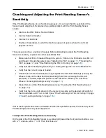
Checking and Adjusting the Print Reading Sensor’s
Sensitivity
If the Print-Reading Sensor is not functioning properly, it may mean that the sensitivity of the
Sensor needs adjustment. Examples of a possible problem with the Print-Reading Sensor
include:
•
Alarm on the HMI: Notice: No Catch Mark
•
Incorrect label cut lengths
•
Incorrect cut locations
•
Double or triple labels, in which the machine appears to ignore where the cut mark
appears at times
These issues can have a number of causes. Before attempting to adjust the Print Reading
Sensor’s sensitivity, explore some other possibilities first:
•
Make sure that film is threaded through the system. If there is no film load a new film roll
and thread it through the system (see “Installing the Film” on page
, and “Fine-Positioning the Film for Cutting” on page
•
Verify that the Print-Reading Sensor Eye is looking through the slot in the Mandrel Fin.
•
Verify that the correct recipe is loaded.
•
Check that the Film Drive Wheels are tight against the Film Drive Bearings (causing the
Wheels to slip on the label and thus preventing them from advancing the film with
precision). If needed, adjust the position of the Film Drive Wheels (see “Film Drive
Wheels: Unlocking/Adjusting/Locking” on page
•
Clean the Lens of the Print-Reading Sensor (see “Cleaning the Print Reading Sensor”
•
Verify that the Cut Length shown for the recipe is the same as the desired cut length for
the actual labels, and if not, correct it (see “Fine-Positioning the Film for Cutting” on page
and “Loading a Recipe” on page
If all of these options have been exhausted and the same problems persist, the sensitivity of the
Print-Reading Sensor may need adjustment.
To Adjust the Print-Reading Sensor’s Sensitivity
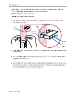
On the side of the Print-Reading Sensor is a yellow light (toward the front) and two buttons, one
with a “+” and one with a “-” on it. Their functions are:
Summary of Contents for LX-150
Page 1: ...LX 150 Shrink Sleeve Label Applicator User Guide ...
Page 2: ...2 Abbreviations 4510001 REV B 220620 ...
Page 4: ...4 Abbreviations 4510001 REV B 220620 ...
Page 12: ...12 Abbreviations 4510001 REV B 220620 ...
Page 76: ...76 Installation 4510001 REV B 220620 ...
Page 132: ...132 Setup 4510001 REV B 220620 ...
Page 146: ...146 Operation 4510001 REV B 220620 ...
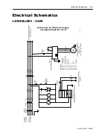
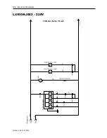
Page 186: ...186 Electrical Schematics 4510001 REV B 220620 LX150N J002 220V Indicator Lamp Circuit ...
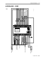
Page 187: ...Electrical Schematics 187 4510001 REV B 220620 LX150N J003 220V PLC ...
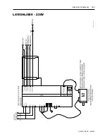
Page 189: ...Electrical Schematics 189 4510001 REV B 220620 LX150N J005 220V ...
Page 190: ...190 Electrical Schematics 4510001 REV B 220620 LX150N J006 220V ...
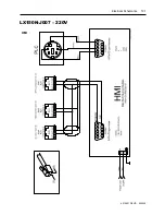
Page 191: ...Electrical Schematics 191 4510001 REV B 220620 LX150N J007 220V HMI ...
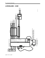
Page 192: ...192 Electrical Schematics 4510001 REV B 220620 LX150N J008 220V UR1 Unwind Circuit ...
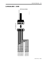
Page 193: ...Electrical Schematics 193 4510001 REV B 220620 LX150N J009 220V UR1 Unwind Cable ...
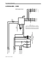
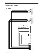
Page 194: ...194 Electrical Schematics 4510001 REV B 220620 LX150N J010 220V Film Roll Motor ...
Page 195: ...Electrical Schematics 195 4510001 REV B 220620 LX150N J011 220V Timing Screw Motor Drive ...
Page 196: ...196 Electrical Schematics 4510001 REV B 220620 LX150N J012 220V Timing Screw Motor ...
Page 197: ...Electrical Schematics 197 4510001 REV B 220620 LX150N J013 220V Brushdown Circuit ...
Page 200: ...200 Electrical Schematics 4510001 REV B 220620 LX150N J016 220V PLC I O Extension ...
Page 202: ...202 Electrical Schematics 4510001 REV B 220620 LX150N J002 480V Indicator Lamp Circuit ...
Page 203: ...Electrical Schematics 203 4510001 REV B 220620 LX150N J003 480V PLC ...
Page 205: ...Electrical Schematics 205 4510001 REV B 220620 LX150N J005 480V ...
Page 206: ...206 Electrical Schematics 4510001 REV B 220620 LX150N J006 480V ...
Page 207: ...Electrical Schematics 207 4510001 REV B 220620 LX150N J007 480V HMI ...
Page 208: ...208 Electrical Schematics 4510001 REV B 220620 LX150N J008 480V UR1 Unwind Circuit ...
Page 209: ...Electrical Schematics 209 4510001 REV B 220620 LX150N J009 480V UR1 Unwind Cable ...
Page 210: ...210 Electrical Schematics 4510001 REV B 220620 LX150N J010 480V Film Roll Motor ...
Page 211: ...Electrical Schematics 211 4510001 REV B 220620 LX150N J011 480V Timing Screw Motor Drive ...
Page 212: ...212 Electrical Schematics 4510001 REV B 220620 LX150N J012 480V Timing Screw Motor ...
Page 213: ...Electrical Schematics 213 4510001 REV B 220620 LX150N J013 480V Brushdown Circuit ...
Page 216: ...216 Electrical Schematics 4510001 REV B 220620 LX150N J016 480V PLC I O Extension ...
Page 219: ...Diagrams and Parts Lists 219 4510001 REV B 220620 Dancer Assembly ...
Page 221: ...Diagrams and Parts Lists 221 4510001 REV B 220620 Cutter Assembly ...
Page 225: ...Diagrams and Parts Lists 225 4510001 REV B 220620 Applicator Assembly ...
Page 227: ...Diagrams and Parts Lists 227 4510001 REV B 220620 LX 150 Frame ...
Page 229: ...Diagrams and Parts Lists 229 4510001 REV B 220620 Head Height Adjust ...
Page 235: ...Diagrams and Parts Lists 235 4510001 REV B 220620 Support and Film Drive Wheel Assemblies ...
Page 238: ...238 Diagrams and Parts Lists 4510001 REV B 220620 400mm Timing Screw Assembly ...
Page 240: ...240 Diagrams and Parts Lists 4510001 REV B 220620 ...

