background image


Page 8 

16/05/2019 


R01.0 


The magnet, connected to the support, creates a force which attracts reps. releases the 
oscillating plate dependent on the oscillation frequency of the power supply. 

The pulsating movement of the oscillation plate causes the material to jump from the rail 
at each oscillation and is conveyed as a result of the angle of inclination of the leaf springs. 

On a cycle of the 50 Hz alternating current supply, the magnet achieves twice its maximum 
pulling  force  while  this  is  independent  of  the  direction  of  the  current  flow.  The  magnet 
thereby produces an oscillating frequency of 100Hz. This 100Hz oscillation is necessary 
to achieve a smooth and gentle transport for small or light work pieces. 

With heavy or large work pieces however, it is necessary to use an oscillating frequency 
of 50Hz. A half-wave of the mains supply is thereby blocked. 
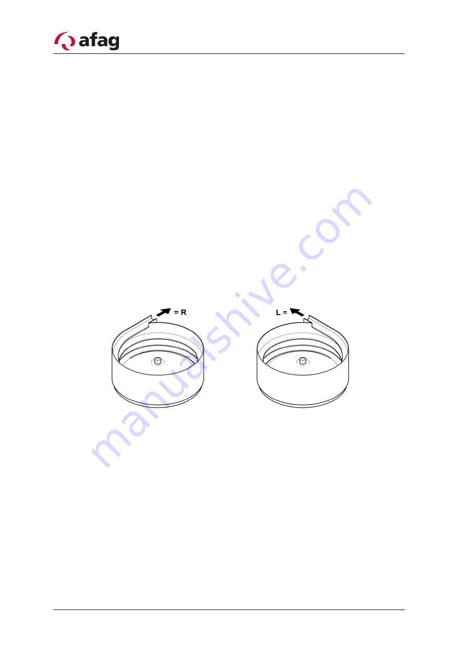
 

2.3


Definition of the feed direction 

The feed directions for the WV are defined as follows:


Left-hand (L)

, in 

anti-clockwise 

direction 

Right-hand (R)

, in 

clockwise 

direction


Figure 


Summary of Contents for WV 630-1

Page 1: ...Bowl feeder WV 630 1 Translation of operating and installation instructions Copyright by Afag GmbH ...

Page 2: ... 05 2019 R01 0 This operation instruction applies to Type Order number Bowl feeder WV630 1 230 V 50 Hz Right 50455916 Left 50470026 Version of Documentation BA_WV630 1_R01 0_EN docx Release R01 0 Date 16 05 2019 ...

Page 3: ...ical data 9 3 Assembly instructions 10 3 1 Transport 10 3 2 Installing the unit 10 3 3 Requirements for the bowl 11 3 4 Information for the construction of selection elements 11 3 5 Power supply 11 4 Operating instructions 12 4 1 Correlations between the transport speed and the WV spring packages 12 4 2 Torques 14 5 Maintenance guidelines 15 5 1 Troubleshooting and fault repair 15 5 2 Cleaning 17 ...

Page 4: ...n immediate threatening danger Non compliance with this information can result in death or seri ous personal injuries invalidity WARNING Indicates a possible dangerous situation Non compliance with this information can result in death or seri ous personal injuries invalidity CAUTION Indicates a possibly dangerous situation Non compliance with this information can result in damage to property or li...

Page 5: ...ended for storing transporting separating and arranging compo nent parts of different sizes forms and materials The workpieces must meet the following requirements in order to ensure a problem free operation they must be free of oil grease and burrs they must not be sticky they must not be statically charged they must not be magnetic no self magnetism they must be free of dirt and not be mixed wit...

Page 6: ...he DGUV regulation 15 The definitions of Section 12 Indirect Effects Medical Implants remain unaffected by the above The alternating magnetic fields that occur in the immediate vicinity of certain vibration convey ors may affect the proper functions of active implants i e pacemakers and defibrillators Any one with active medical implants for which no individual risk assessment has been provided mu...

Page 7: ... bowl should not exceed the value specified in chapter 2 4 as this cannot ensure optimum transport behaviour 2 2 Functional description A Bowl Feeder is a unit which transforms magnetic oscillations in order to use the feeding of work pieces The basic construction of a bowl feeder comprises the following elements see Figure 1 1 Material to be conveyed 2 Conveyor line 3 Leaf spring 4 Projectile dir...

Page 8: ...t supply the magnet achieves twice its maximum pulling force while this is independent of the direction of the current flow The magnet thereby produces an oscillating frequency of 100Hz This 100Hz oscillation is necessary to achieve a smooth and gentle transport for small or light work pieces With heavy or large work pieces however it is necessary to use an oscillating frequency of 50Hz A half wav...

Page 9: ...tandard number of springs Number per spring assembly 4 x 8 Spring dimensions length gauge for boreholes x width mm 140 116 x 40 Spring thickness mm 2 Quality of the spring fastening screws 12 9 Tightening torque spring fastening screws Nm 135 Maximum weight of the oscillating units depending on the mass moment of iner tia and required running speed kg 30 Environmental conditions for operation Temp...

Page 10: ...ring transport the bowl feeder must only be held by the base Neither the bowl nor the selection elements are lifting points 3 2 Installing the unit For operation the WV must always be mounted on a sufficiently pro portioned foundation The type of fixing can be seen in the following drawings WV with base plate see Figure 3 WV with base plate and mounting foot see Figure 4 WV with base plate and adj...

Page 11: ...cillating system After the construction of selection elements the oscillation system must always be re tuned to achieve an optimum conveying capacity Increasing of the conveying capacity by means of increasing the amplitude has an ex tremely negative effect on the system Broken springs or inadmissible temperature in crease of the magnetic coil could be the result 3 5 Power supply WARNING Any work ...

Page 12: ...t Selection ele ments always present additional weight e outlet in the bowl f support g environment are there other oscillating components with a disturbing influence Procedure for adjustment of the oscillating system WARNING Before removing the casing unplug the mains cable 1 check that the correct control unit is connected Observe the Operating instructions phase control unit 2 Remove the casing...

Page 13: ...is increased a remove springs b the procedure and sequence are the same as for inserting springs Irregular transport speed at bowl perimeter a a spring must be removed from the slower location b a spring must be inserted at the faster location Erratic transport speed between two spring packages a seen from the direction of transport a spring must either be removed or inserted behind the area of er...

Page 14: ...w Strength class 8 8 Strength class 10 9 Strength class 12 9 M4 2 8 4 1 4 8 M5 5 5 8 1 9 5 M6 9 5 14 0 16 5 M7 15 5 23 0 27 0 M8 23 0 34 0 40 0 M10 46 0 68 0 79 0 M12 79 0 117 0 135 0 M14 125 0 185 0 215 0 M16 195 0 280 0 330 0 M18 280 0 390 0 460 0 M20 390 0 560 0 650 0 M22 530 0 750 0 880 0 M24 670 0 960 0 1120 0 M27 1000 0 1400 0 1650 0 M30 1350 0 1900 0 2250 0 by Dubbel 18th edition page G175 ...

Page 15: ...diately NOTE Check all visible screws for tightened 5 1 Troubleshooting and fault repair WARNING Electrical work must only be carried out by trained personnel Before removing the casing unplug the power cable Interruptions caused by defective components must be repaired by replacing the defective component only NOTE Defective components must only be replaced by Afag original spare parts See chapte...

Page 16: ...ir gap between the magnetic coil and the anchor bolt is no longer correct Remove the casing and readjust the air gap Spring broken Remove the casing and replace the broken spring Regulator on control unit has moved Readjust regulator Bowl feeder develops loud noises Cause of fault Fault repair The casing has become loose Tighten all casing screws The magnetic coil or anchor bolt have be come loose...

Page 17: ...er vacuum cleaner Habasit white dark green Polyurethane red yellow Nextel Alcohol or spirit Clean with a damp cloth and let it dry Don t fill detergent into bowl Don t placed bowl into a cleaning bath 5 3 Wear and Spare parts Table 2 Wear parts Pos Type 146 Leaf spring 202 Rubber buffer 184 Shims 190 Clamping plate 226 Screw 120 122 Chip protection ring Table 3 Spare parts Pos Type Designation 236...

Page 18: ...Page 18 16 05 2019 R01 0 ...

Page 19: ... due to mag net current and thus magnetic force variability Soft starting all IRG and MSG types can be mounted in various different ways and offer extra controls for photoelectric barriers initiator elements or extern 24VDC signal For a detailed description of the controllers refer full range catalogue from AFAG GmbH Third party controllers can also be used as long as they meet the technical requi...

Page 20: ...fag GmbH Wernher von Braun Straße 1 D 92224 Amberg Tel 49 0 96 21 65 0 27 0 Fax 49 0 96 21 65 0 27 490 Sales sales afag com www afag com Switzerland Afag Automation AG Zuführtechnik Fiechtenstrasse32 CH 4950 Huttwil Tel 41 0 62 959 86 86 Fax 41 0 62 959 87 87 ...

Page 21: ...2019 Page 21 7 Disposal WF feeders that are no longer in use should not be disposed of as complete units but dismantled into separate materials and recycled Non recyclable components must be dis posed of correctly ...

Reviews: