background image

ROBOTAPE 50 ME - LH

Production manager

A qualified and skilled technician with experience in the operation and use of machinery in the relevant

manufacturing field.

According to the production needs, the Supervisors may use the machine themselves or give the task to

another Operator.

1.4. MODES OF REQUESTING FOR ASSISTANCE

The distribution network

ROBOPAC

is at your service for any problem that requires technical support, to order

spare parts, and for whatever new type of need that can help develop your business.

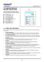
Report the data displayed on the ID plate, the estimated hours you have used the machine, and the type of

flaw you have uncovered when requesting technical support.
Contact one of our authorized dealers at the listed address for all your needs.

ROBOPAC SPA

VIA FABRIZIO DA MONTEBELLO, 81

47892 GUALDICCIOLO, REPUBBLICA S.MARINO (RSM)

Phone  0549 (interna+378) 910511

Fax  0549/908549 - 905946

http://www.aetnagroup.com

1.5. ATTACHED DOCUMENTATION

The machine is provided with the documentation listed below, in the absence of a different trade agreement.

CE statement of conformity.

Warranty conditions (included in this booklet).

Instructions for unpacking and installation.

Quick start guide.

Wiring diagram and list of components.

Manuals of installed commercial devices (if necessary for machine use).

USB flash drive that contains the information listed.

Use and maintenance manual translated into various languages.

Spare parts catalogue.

1.6. HOW TO READ THE DIRECTIONS FOR USE

The handbook is divided in chapters, each of which describes a specific category of information.

Each operator who interacts with the machine, apart from reading all the documentation, must read and learn

the information concerning his specific qualification.

Refer to the name preceding the title of the chapters, present in the summary, to search for the subjects to

consult.

These instructions are the result of an automatic system of assembly of text and illustrations, therefore, it is

possible to find, as pages change, some interruptions of the flow of text and charts.

Keep this manual for the entire duration of its useful life in a well known and easy to access place, available

for reference any time the need should arise.

Keep the instructions for use and the attached documentation for future consultation.

6/43

Summary of Contents for ROBOPAC ROBOTAPE 50 ME - LH

Page 1: ...2249 0 English Edition 1116 Serial number __ __ __ __ __ __ __ __ __ __ ____________________________________________________________________________________________________ Important Read and understa...

Page 2: ...ION OF THE OPERATION CYCLE 3 3 SAFETY DEVICE DESCRIPTIONS 3 4 DESCRIPTION OF THE ELECTRICAL DEVICES 3 5 DESCRIPTION OF ACCESSORIES ON REQUEST 3 5 1 DESCRIPTION OF THE TAPING UNIT 3 6 TECHNICAL SPECIFI...

Page 3: ...BLE 7 3 LUBRICATION POINT DIAGRAM 8 TROUBLESHOOTING 8 1 TROUBLES CAUSES REMEDIES 8 2 CORRECTING TAPING ERRORS 9 SPARE PARTS REPLACEMENT INFORMATION 9 1 RECOMMENDATIONS FOR REPLACING PARTS 9 2 REPLACEM...

Page 4: ...specify the message Translation of the original instruction Keep this manual for the entire duration of its useful life in a well known and easy to access place available for reference any time the n...

Page 5: ...lified technician a person authorised and chosen from those who have the requirements skills and information necessary for installation use and extraordinary maintenance of the machine Operator A pers...

Page 6: ...de agreement CE statement of conformity Warranty conditions included in this booklet Instructions for unpacking and installation Quick start guide Wiring diagram and list of components Manuals of inst...

Page 7: ...e during transport and or storage must fall within the range allowed in order to prevent damaging the electrical components Install the machine ONLY in spaces free of explosion and or fire risks Avoid...

Page 8: ...e machine immediately and restart it only after the normal conditions of use have been restored DO NOT carry out interventions different from those indicated in the user manual without the written con...

Page 9: ...the required training and meet the suitable conditions for carrying out the activities in safety conditions The employer must inform the operator on the INCORRECT USES predictable and on the persisten...

Page 10: ...50 ME LH Danger of arms crushing do not put your hands inside the moving organs Danger of entanglement Do not get close to the conveying belts to avoid getting entangled with parts of the body or clot...

Page 11: ...ty level unchanged Use lubricants oils or grease recommended by the manufacturer or with similar chemical physical features Do not dump into the environment polluting liquids worn parts and maintenanc...

Page 12: ...essary replace them with new ones that shall be positioned in the same places as previously 2 8 SURROUNDING AREAS The illustration depicts the perimeter work areas of the machine A Operator s working...

Page 13: ...tor or other persons who come into contactwith the machine in any way The machine is produced in a range ofdifferent models in order to suit market requirements This machine is normally installed in w...

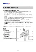
Page 14: ...ce box A at the inlet of machine B between the conveyor belts 2 After start up the machine automatically seals the top and the bottom of the box 3 The operator picks up the box exiting the machine The...

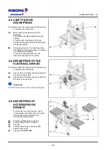
Page 15: ...cated by the arrow 3 4 DESCRIPTION OF THE ELECTRICAL DEVICES The figure shows the positioning of the devices on board of the machine A gear motor it enables the movement of the left conveyor belt B ge...

Page 16: ...also possible to adjust the length of the front flap as needed DESCRIPTION OF COMPONENTS 1 Roll hub 2 Spring adjustment screws 3 Knurled nonreturn roller 4 Return roller 5 Tape shaper spring 6 Small...

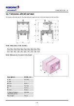
Page 17: ...the machine Table dimensions of the machine A mm B mm C mm D mm E mm F mm G mm H mm L mm M mm 925 960 565 745 670 850 325 775 380 830 Table Dimensions of product to be taped Description 50 ME LH L mi...

Page 18: ...0 24 75 3 Lm Average level of pressure on the measurement surface Lw Acoustic power output Lop Level at the operator s place i Caution Warning Prolonged exposure over 80 dB A may cause health problem...

Page 19: ...flat surface steady and without vibrations with adequate weight supporting capacity also in consideration of the palletised loads to be wrapped The area must be equipped with a power supply socket i D...

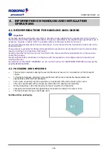
Page 20: ...nual and those applied directly to the machine and or the package Provide suitable safety conditions in compliance with the regulations on workplace safety to prevent and minimise the risks Pay attent...

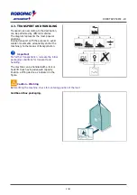
Page 21: ...ovements adequately anchor the machinery to the means of transportation Important For further transportation recreate the initial packaging conditions for transport and handling The machine can be han...

Page 22: ...as indicated 1 Lift the machine See 4 3 transport and handling 2 If the machine is equipped with swivel wheels F screw them onto the feet 3 If necessary identify the exact position and trace the co o...

Page 23: ...p taping unit by lowering the stopper G i Danger Warning The blade is very sharp 6 Operate screws E to move feet D and level the machine see 6 9 setting the workbench height 7 Remove the lifting bars...

Page 24: ...and lower taping unit 1 Position the roll of adhesive tape on the roll holder Important Make sure the adhesive surface is in the correct position 2 Glue the tape provided to the tape pull 3 Insert the...

Page 25: ...ssary to perform an overall control to verify if said requirements have been complied with 4 7 ELECTRICAL CONNECTION Proceed as follows for electrical connections 1 Check that the mains voltage V and...

Page 26: ...he devices that could if activated produce unexpected danger conditions provoking hazards to personal safety and health 5 2 CONVEYOR BELT ADJUSTMENT Proceed as indicated 1 Deactivate the main electric...

Page 27: ...rtant To check chain tension use the method indicated in the illustration The resulting shift R should be 10 15 mm i Caution Warning Before re starting the machine check that no tools or other equipme...

Page 28: ...B 2 Operate the screw C to centre the tape 3 Tighten the nut B 5 4 3 ADJUSTMENT OF TAPE PRESSURE ON THE CASING Adjust the main spring D 1 Loosen nut E 2 Operate the nut F to adjust the tension of the...

Page 29: ...obtain performances different from the intended ones 6 2 CONTROL DESCRIPTION The illustration shows the main controls of the machine and the list shows their description and function A Emergency stop...

Page 30: ...features with respect to previous ones you must perform some adjustments on the machine The interventions which may be performed are indicated as follows Conveyor belt positioning Positioning of side...

Page 31: ...pect to taping unit N capsize the side press rolls as shown in the figure 2 Loosen knobs B and open side pressure guides Y to allow introduction of the box 3 Place the box below the support of taping...

Page 32: ...port and handling 2 Loosen screws U adjust supporting leg V to the desired height and then tighten screws 3 Read the value indicated on gradutaed scale Z 4 Repeat the same operations on the other supp...

Page 33: ...ns but dispose them according to the standards in force Before performing any maintenance operation disconnect the power supply 7 2 MAINTENANCE PERIOD TABLE Important Keep the machinery in maximum eff...

Page 34: ...k efficiency and if necessary replace See 9 5 blade replacement iDanger Warning The blade is very sharp Every 2000 hours Transport unit driving chain General inspection Check for wear and if necessary...

Page 35: ...L 460 IP SPARTAN EP 460 ESSO BLASIA 460 AGIP MOBILGEAR 634 MOBIL OMALA EP 460 SHELL ENERGOL GR XP 460 BP Worm gear motor Grease TELESIA COMPOUND B IP STRUCTOVIS P LIQUID KLUBER TOTALCARTER SYOO TOTAL...

Page 36: ...sitioning The sealing tape is not centred on the box The transmission chain of the transport unit moves too slow The adhesive tape is not positioned correctly on the taping unit Adjust the tension of...

Page 37: ...ape curls Remedy Always Upper unit adjust the height of the upper head approximately 3 mm from the box Problem Tape creases Remedy Make sure the rollers turn freely Make sure the friction on the roll...

Page 38: ...danger conditions provoking hazards to personal safety and health When replacing worn parts use only original replacement parts The Manufacturer is not responsible for any damage to property or injuri...

Page 39: ...and lift the roller R to completely loosen the chain S 3 Remove the split link T and remove the chain S 4 Install the new chain and close it with the split link 5 Adjust chain tension See 5 3 how the...

Page 40: ...5 REPLACING THE BLADE 1 To replace the blade raise the guard A as shown in the figure 2 Loosen the screws B 3 Remove the blade C 4 Insert the new blade making sure the sharp side is correctly position...

Page 41: ...ubricant oil and non iron components rubber PVC resins etc in the environment Discharge them in compliance with current regulations Useful information for the disposal of machines and machine parts Sc...

Page 42: ...any losses due to lack of production or injuries to persons or damage to things caused by malfunctions or forced suspension in using the machine covered by the warranty THE WARRANTY DOES NOT COVER dam...

Page 43: ...T kg IS IN CONFORMITY WITH DIRECTIVES DIRECTIVE 2006 42 EC OF THE EUROPEAN PARLIAMENT AND OF THE COUNCIL of 17 May 2006 on machinery and amending Directive 95 16 EC DIRECTIVE 2014 30 EU OF THE EUROPEA...

Reviews: