


204T
Cod.006.0001.1439
13/05/2013 v2.4
ENGLISH
0
11/31
8
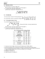
SET-UP (INITIAL SET-UP OF THE WELDING POWER SOURCE)
Set the welding power source ON/OFF switch to “O” to switch the unit off.
S3
Hold down the button.
Set the welding power source ON/OFF switch to “I” to switch on the unit.
SIMULTANEOUS ACTIONS
Set
The message appears for a few seconds on the following displays: D1
S3
Press the button to confirm.
The value relative to the selected setting appears on the following displays: D1
E1
Using the encoder, edit the value of the selected setting.
Press any key (except S3) to save the setting and quit the menu.
Tab. 1 - Setup settings
SETTING
MIN
DEFAULT
MAX
COOLER ACTIVATION
OFF
AUT
ON
STARTING CURRENT
%
A
A
*1
FINAL CURRENT
%
A
A
*1
HF CURRENT
20 A
SYN
200 A
TYPE OF PULSED CURRENT SLO. (*2)
SLO.
FA. (*3)
PILOT ARC
OFF
OFF
ON
*1: The value of this parameter can be set as a percentage of the welding current or as an absolute value expressed in Amperes.
*2: This setting enables slow pulsed mode.
*3: This setting enables fast pulsed mode.
Cooler activation
ON= The cooler is always running when the power source is switched on. This mode is preferable for heavy duty and automatic welding
procedures.
OFF= The cooler is always disabled because an air-cooled torch is in use.
AUT= When the unit is switched on the cooler is switched on for 16 s. During welding procedures the cooler runs constantly. When welding is
terminated the cooler continues to run for 90 s + a number of seconds equivalent to the average current value shown using the HOLD
function.
HF Current
This parameter establishes the current value during HF discharge. The value of this parameter can be set as an absolute value or in SYN.
With SYN setting the HF current value is calculated automatically on the basis of the preset welding current value.
Consequences of a higher value:
Arc striking is facilitated, even on very dirty workpieces.
Risk of piercing excessively thin gauge workpieces.
Pilot arc
The function enables the output of a low current between the 1st and 2nd times of the torch trigger to shield the mask in advance and avoid the
risk of blinding flashback caused by the welding current.
Summary of Contents for Masterweld 204T
Page 1: ...Cod 006 0001 1439 13 05 2013 v2 4 ENGLISH MASTERWELD 204T Instruction manual GB ...
Page 2: ...Cod 006 0001 1439 13 05 2013 v2 4 ENGLISH 204T 2 31 ...
Page 3: ...204T Cod 006 0001 1439 13 05 2013 v2 4 ENGLISH 0 3 31 ...
Page 25: ...204T Cod 006 0001 1439 13 05 2013 v2 4 ENGLISH 0 25 31 16 MASTERWELD SPARE PARTS ...
Page 27: ...204T Cod 006 0001 1439 13 05 2013 v2 4 ENGLISH 0 27 31 17 ELECTRICAL DIAGRAM 17 1 204T ...
Page 28: ...Cod 006 0001 1439 13 05 2013 v2 4 ENGLISH 204T 28 31 ...
Page 30: ...Cod 006 0001 1439 13 05 2013 v2 4 ENGLISH 204T 30 31 ...
Page 31: ...204T Cod 006 0001 1439 13 05 2013 v2 4 ENGLISH 0 31 31 ...