background image

Master Unit Keypad or Prox

RVT

RVT

RVT

RVT

RVT

RVT

RVT

RVT

101

101

Relay 1

Relay 2

8.000

USB

1

2

3

4

1       2       3

1       2       3

COI L

RVT

RVT

RVT

RVT

RVT

RVT

RVT

RVT

101

101

Relay 1

Relay 2

8.000

USB

IN

+

 2

4V

 -

Auxiliary

1

2

3

4

1       2       3

1       2       3

COI L

RVT

RVT

RVT

RVT

RVT

RVT

RVT

RVT

101

101

Relay 1

Relay 2

8.000

USB

IN

+

 2

4V

 -

Master

Only

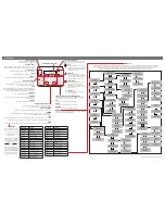
Auxiliary Wiring Connections (Optional)

Keycell Prime 4G

- Advanced GSM Keypad/Prox Reader 

STILL HAVING TROUBLE? 

Find all of our support options such as Web Chat, 

Full Manuals, Customer Helpline and more on 

our website:

WWW.AESGLOBALONLINE.COM

* ALWAYS TEST THE UNIT ON SITE 

BEFORE

INSTALLATION TO AVOID RE-STOCKING FEE * 

See full T&C’s on our website

All connections will be pre-

wired to the ‘Sounder PCB’ 

so you just need to connect each unit together

Detailed wiring diagrams available online.

Auxiliary Units are optional extras. 

Up to

separate units can be added to a 

single

master. 

This will provide a 

maximum of 8 

separate relays to control.

3

Auxiliary Prox

1

2

3

4

ON

DIP

24V            1        2        3

NC         COM         NO                 PTE             

24

V   


  1


  2


  3

1

2

3

4

ON

D

I

P

SLAVE  IN

SLAVE  OUT

1       2       3

1       2       3

IN

+

 2

4V

 -

O

U

T

+

 2

4V

 -

IN

1

 2

 3

O

U

T

1

 2

 3

COI L

Auxiliary Prox and Keypad

12-24v

IN

SLAVE IN

1    2    3

12-24v

OUT

SLAVE OUT

1    2    3

1

2

3

4

ON

DIP

24V            1        2        3

NC         COM         NO                 PTE             

24

V   


  1


  2


  3

1

2

3

4

ON

D

I

P

SLAVE  IN

SLAVE  OUT

1       2       3

1       2       3

IN

+

 2

4V

 -

O

U

T

+

 2

4V

 -

IN

1

 2

 3

O

U

T

1

 2

 3

COI L

Auxiliary Keypad

1

2

3

4

ON

DIP

24V            1        2        3

NC         COM         NO                 PTE             

24

V   


  1


  2


  3

12-24v

IN

SLAVE IN

1    2    3

12-24v

OUT

SLAVE OUT

1    2    3

If the master is the only unit being used keep the ‘jumper’ on for 

the use of both relays on the board.

The jumper link needs to be off for the programming and use of 
auxiliaries.

1

2

3

4

ON

DIP

24V            1        2        3

N C         COM         N O                 PTE             

24

V   


  1


  2


  3

OPEN

Exit Button

(optional)

Auxiliary Unit

1

2

3

4

ON

DIP

24V            1        2        3

NC         COM         NO                 PTE             

24

V   


  1


  2


  3

OPEN

Exit Button

(optional)

Auxiliary Unit

12-24v

IN

SLAVE IN

1    2    3

12-24v

OUT

SLAVE OUT

1    2    3

Master Unit

Remove the 4 x nylon screws and lift 

off the main assembly to access the 

auxiliary out connections if required

Keypad Only

Keypad & Prox or 

Prox Only

1

2

3

4

ON

D

I

P

SLAVE  IN

SLAVE  OUT

1       2       3

1       2       3

IN

+

 2

4V

 -

O

U

T

+

 2

4V

 -

IN

1

 2

 3

O

U

T

1

 2

 3

COI L

12-24v

IN

SLAVE IN

1    2    3

12-24v

OUT

SLAVE OUT

1    2    3

Two cores for 
power and 
three for 
communication

Maximum Distance

CAT 5 cable 

50m per power supply with a max of 2 power supplies

Jumper Link

(Found on Prox and Keypad Boards) 

Send SMS 9999#001# to enable auxiliary unit(s)

Unit(s)

Summary of Contents for Keycell Prime 7 4G

Page 1: ...Keycell Prime 7 4G Advanced GSM Keypad Prox Reader STILL HAVING TROUBLE Find all of our support options such as Web Chat Full Manuals Customer Helpline and more on our website WWW AESGLOBALONLINE COM ALWAYS TEST THE UNIT ON SITE BEFORE INSTALLATION TO AVOID RE STOCKING FEE See full T C s on our website LIGHTNING PRONE AREAS MUST USE SURGE PROTECTION FOR POWER SUPPLY Relay Connections 4 See overlea...

Page 2: ...ON ALWAYS ensure the system is switched OFF when adding or removing your SIM card and ensure the orientation is correct CONNECTION TO NETWORK 4G Quick Flashing Standby Constant ON OFF Searching MODEM LED INDICATOR CHANGE APN for VoLTE 4G services Check with your network provider for the correct APN for 4G data Once you have confirmed the APN enter it in place of APNinfo in an SMS to the intercom v...

Page 3: ...T 24V IN 1 2 3 O UT 1 2 3 COIL Auxiliary Prox and Keypad 12 24v IN SLAVE IN 1 2 3 12 24v OUT SLAVE OUT 1 2 3 1 2 3 4 ON DIP 24V 1 2 3 NC COM NO PTE 24V 1 2 3 1 2 3 4 O N D I P SLAV E IN SLAV E OUT 1 2 3 1 2 3 IN 24V O UT 24V IN 1 2 3 O UT 1 2 3 COIL Auxiliary Keypad 1 2 3 4 ON DIP 24V 1 2 3 NC COM NO PTE 24V 1 2 3 12 24v IN SLAVE IN 1 2 3 12 24v OUT SLAVE OUT 1 2 3 If the master is the only unit b...

Page 4: ... dip switch configuration of the auxiliary it wants to trigger Auxiliary Device Relay Setup Relay 3 Relay 4 Relay 5 Relay 6 Relay 7 Relay 8 ON DIP 1 2 3 4 ON DIP 1 2 3 4 ON DIP 1 2 3 4 ON DIP 1 2 3 4 ON DIP 1 2 3 4 ON DIP 1 2 3 4 91 RelayNumber Relay Number 3 8 Sounder Board Prox Board 4 Keycell Prime 7 4G Advanced GSM Keypad Prox Reader STILL HAVING TROUBLE Find all of our support options such as...

Page 5: ...Add additional app users Choose your device from the list provided Customise Advanced Features more on this on pg4 If you are having trouble the help section has troubleshooting and How to Videos to help you resolve the problem Keycell Prime 4G Advanced GSM Keypad Prox Reader STILL HAVING TROUBLE Find all of our support options such as Web Chat Full Manuals Customer Helpline and more on our websit...

Page 6: ...Y Relay Number 3 8 X Relay time 1 9999 seconds 9999 05XY Note Advanced programming available in full manual Tip New programming app due to release late 2021 Please note by installing this product you are accepting the following warranty terms 1 The manufacturer s warranty is a return to base 2 year warranty from date of manufacture This means that any suspected defective components or items are re...

Page 7: ...port options such as Web Chat Full Manuals Customer Helpline and more on our website WWW AESGLOBALONLINE COM ALWAYS TEST THE UNIT ON SITE BEFORE INSTALLATION TO AVOID RE STOCKING FEE See full T C s on our website Reset Default Unit 1 Power off the unit approx 60 secs 2 Make a link across the terminals marked OPEN 3 Switch on power 4 After several seconds the relay will click 5 The unit will then c...

Reviews: