background image

12

FP8419K_IG_en-GB_v1

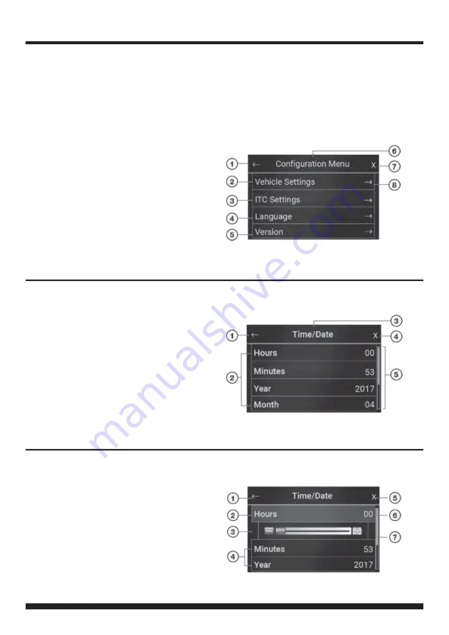
MENU NAVIGATION

Main Menu Navigation

1. Return to previous menu
2. Enter

Vehicle Settings

menu

3. Enter

ITC Settings

menu

4. Enter

Language

menu

5. Enter

Module Version

menu

6. Header
7. Close menu settings
8. Enter Sub-menufor selected option

Sub-Menu Navigation

1. Return to previous menu
2. Sub-menuconfiguration options
3. Header
4. Close menu
5. Scroll bar (Scroll Up/Downfor moreoptions)

Setting Configuration Options

1. Return to previous menu
2. Setting highlightedwhen selected
3. Scroll bar (Use to customise setting)
4. Press to select option
5. Close menu
6. Current value (Adjust with slider)
7. Scroll bar (Scroll Up/Downfor moreoptions)

Press the MENU button to access the Configurationmenuand adjust Vehicle, ITC Interface, Language and
Version settings.

The following screenshots are sample menu displays to assist in the navigation of the user interface. Use
the Return Arrow to go back to the previous menu. Press the X to close the menu window and return to the
TFT colour touch screen home screen. For further setting options, refer to the charts in the following pages
of this manual.

Summary of Contents for FP8419K

Page 1: ...ubject to change without notice due to manufacturer changes and or improvements to the product s This instruction manual is based on documented data and research The manufacturer of this product canno...

Page 2: ...1 Remove the two passenger and driverside knee panels on the lower console A Next remove the two exposedscrews B 2 Using a panel removal tool carefully remove the tray located below the USB and 12Vso...

Page 3: ...ugand removethe panel 6 Remove the OEM display and the CDreceiver by unscrewing the four screws for each component then unplugall wiring and remove 7 Carefully cut and remove the highlighteddashed are...

Page 4: ...dback cover NB The amountof screws mayvary betweenvehicle models Retain the 12Vsocket fromthe OEM panelandplace it on the aftermarket panel once removedfromthe OEM panel 9 Remove the five screws secur...

Page 5: ...rto removethe ignition controls 12 Place the drive train ignitioncontrol triminto the fascia panel 13 Place the OEM drive train ignitioncontrol buttons retained in Step 11 into the trimfrom Step 12 Ne...

Page 6: ...he back of the buttons being careful not to knockover the spacers placed in the previous step 15 Carefully align the circuit board over the rubber pad 16 Place the back cover plate over the PCB and se...

Page 7: ...the brackets B Lastly secure stereo assembly intodash cavity C 18 Connect and reassemble everything in the reverse orderof disassembly to complete the installation NB 12V cigarette plugis retained fro...

Page 8: ...eer Units with Vocie Command Capabilities 6 Mute 7 Hang Up BT HU Only 8 Pick Up BT HU Only Here are some exampleof how to makevarious patch leads Example 1 Alpine Cut Link J2 then use the Jack Connect...

Page 9: ...Harness SWC See Connecting the Patch Lead To Back of ITC Display Reverse Video Input Brown To Vehicle Harness Behind Screen For Both 4 2 8 Monitors Attach to Sync Box Audio Aux White Audio Aux Red ToC...

Page 10: ...toutside air or odors fromentering Note Operatingthis function when the A Cis off in creases humidityandmaycause the windowsto fog This feature is not available whenDefrost orDefog modesare active HH...

Page 11: ...al tem peratures 15 Increase fan speed using the Fan button 23 0 22 0 DUAL AUTO AUTO 16 Decrease the fan speed using the Fan button 17 Toggle AUTO on to engage Auto mode for all functions Air Directio...

Page 12: ...previous menu 2 Setting highlightedwhen selected 3 Scroll bar Use tocustomisesetting 4 Press to select option 5 Close menu 6 Current value Adjust with slider 7 Scroll bar Scroll Up Downformoreoptions...

Page 13: ...thenotification Installer MenuEnabled Use the charts onthe followingpages of this instruction manual tonavigate throughthe various menusand settings offeredby the kit Set CameraType to Type2 for Must...

Page 14: ...14 FP8419K_IG_en GB_v1 ITC SETTINGS CHART LANGUAGE SOFTWARE SETTINGS CHART...

Page 15: ...15 FP8419K_IG_en GB_v1 NOTES...

Page 16: ...16 FP8419K_IG_en GB_v1 NOTES...

Reviews: