Mechanical Specifications and Installation
PRO280LM Hardware Manual
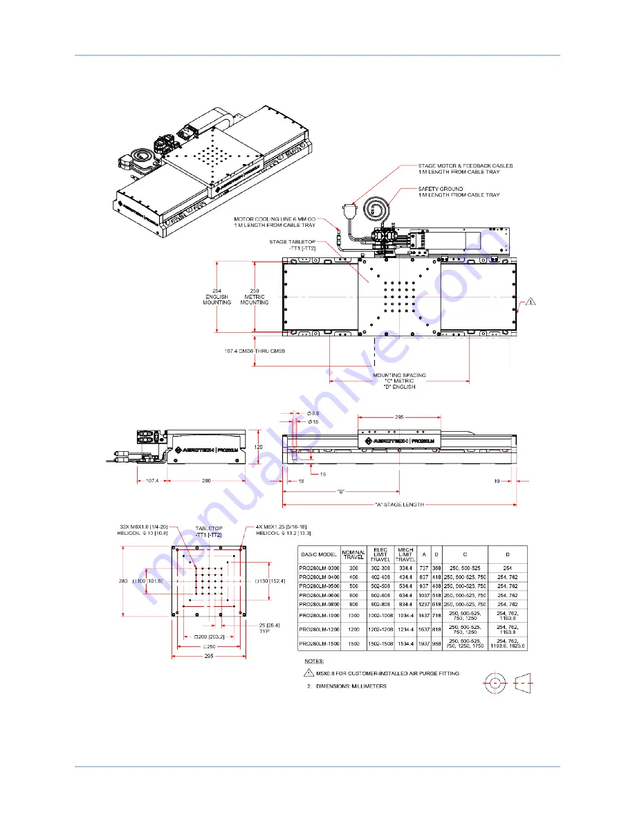
2.2. Dimensions
Figure 2-3:
PRO280LM Dimensions
20
Chapter 2
www.aerotech.com
Page 1: ...Revision 1 04 00 PRO280LM Hardware Manual...
Page 2: ...ech com Phone 1 412 967 6440 Fax 1 412 967 6870 101 Zeta Drive Pittsburgh PA 15238 2811 www aerotech com United Kingdom China Email Support aerotech com Phone 44 0 1256 855055 Fax 44 0 1256 855649 Ema...
Page 3: ...g and Handling the Stage 17 2 2 Dimensions 20 2 3 Securing the Stage to the Mounting Surface 23 2 4 Attaching the Payload to the Stage 24 2 4 1 Speed Capability 25 Chapter 3 Electrical Specifications...
Page 4: ...oad Capability of PRO280LM Series Stages 25 Figure 2 7 Stage Orientations 25 Figure 3 1 Ground Connection Points for the CMS0 Option 28 Figure 3 2 Motor and Feedback Wiring 34 Figure 3 3 Motor and Fee...
Page 5: ...29 Table 3 3 Feedback Connector Pinout E1 and E2 Options 30 Table 3 4 Mating Connector Part Numbers for the Feedback Connector 30 Table 3 5 Feedback Connector Pinout E3 Option 31 Table 3 6 Mating Con...
Page 6: ...Table of Contents PRO280LM Hardware Manual 6 www aerotech com This page intentionally left blank...
Page 7: ...e followed 1 Access to the PRO280LM and component parts must be restricted while connected to a power source 2 Do not connect or disconnect any electrical components or connecting cables while connect...
Page 8: ...Safety PRO280LM Hardware Manual 8 www aerotech com This page intentionally left blank...
Page 9: ...urther more declares that it is not allowed to put the equipment into service until the machinery into which it is to be incorporated or of which it is to be a component has been found and declared to...
Page 10: ...Declaration of Conformity PRO280LM Hardware Manual 10 www aerotech com This page intentionally left blank...
Page 11: ...travel stage 1500 1500 mm travel stage Mounting Orientation Required Normal mounting orientation MT1 Side mounted or vertical orientation MT2 Inverted mounting orientation Tabletop Required TT1 Tablet...
Page 12: ...ver be ordered on the upper axis of an XY set only order on lower axis ThermoComp Optional TCMP ThermoComp integrated thermal compensation single or lower axis NOTE An A3200 controller must be used wi...
Page 13: ...onment Excessive floor or acoustical vibration can affect system performance Contact Aerotech for information regarding your specific application Protection Rating The PRO280LM stages have limited pro...
Page 14: ...sec 60 rad 12 4 arc sec 70 rad 14 4 arc sec 78 rad 16 1 arc sec Roll 49 rad 10 1 arc sec 60 rad 12 4 arc sec 70 rad 14 4 arc sec 78 rad 16 1 arc sec Yaw 49 rad 10 1 arc sec 60 rad 12 4 arc sec 70 rad...
Page 15: ...c sec Yaw 90 rad 18 6 arc sec 110 rad 22 7 arc sec 120 rad 24 7 arc sec 130 rad 26 8 arc sec Maximum Speed 2 2 m s Maximum Acceleration 2 3 g Maximum Force Continuous 266 2 N Standard 437 1 N With Air...
Page 16: ...lyethylene gloves to prevent any contaminants from adhering to the surface of the PRO280LM 3 During installation use cleaned vented stainless steel fasteners when securing the PRO280LM 4 Reduced air p...
Page 17: ...ooth flat and clean surface Before operating the PRO280LM it is important to let it stabilize at room temperature for at least 12 hours Allowing it to stabilize to room temperature will ensure that al...
Page 18: ...ual Figure 2 1 Shipping Brackets Used on Single Axis Stages or Upper Axes of XY Systems N OTE After removing the shipping brackets retain them for future use Do not transport or ship the PRO280LM with...
Page 19: ...e threaded into the stage base These must be removed for the stage to operate Retain the lifting hardware for future use If the stage must be lifted in the future reattach the shipping brackets and th...
Page 20: ...Mechanical Specifications and Installation PRO280LM Hardware Manual 2 2 Dimensions Figure 2 3 PRO280LM Dimensions 20 Chapter 2 www aerotech com...
Page 21: ...PRO280LM Hardware Manual Mechanical Specifications and Installation Figure 2 4 PRO280LM Accessory Tabletop Dimensions TT3 TT6 Options www aerotech com Chapter 2 21...
Page 22: ...Mechanical Specifications and Installation PRO280LM Hardware Manual Figure 2 5 Dimensions for Stages without a Cable Management System CMS0 Option 22 Chapter 2 www aerotech com...
Page 23: ...place the stage on the mounting surface N OTE The PRO280LM is precision machined and verified for flatness prior to product assembly at the factory If machining is required to achieve the desired flat...
Page 24: ...propriate and servo instability can occur Refer to the controller help file for tuning assistance The payload must be flat rigid and comparable to the stage in quality to maintain optimum performance...
Page 25: ...for the PRO280LM Achievable speeds are application dependent and determined by factors such as travel length payload amplifier sizing and duty cycle The Motor Sizer application supplied by Aerotech at...
Page 26: ...Mechanical Specifications and Installation PRO280LM Hardware Manual 26 Chapter 2 www aerotech com This page intentionally left blank...
Page 27: ...ually indicate the appropriate connections If system level integration was purchased an electrical drawing showing system interconnects has been supplied with the system separate from this documentati...
Page 28: ...is stage into the final application D A N G E R Remove power before connecting or disconnecting electrical components or cables Failure to do so may cause electric shock or damage to the equipment W A...
Page 29: ...e B A3 Motor Phase C 1 Reserved 2 Reserved 3 Reserved 4 Reserved 5 Reserved A4 Frame ground motor protective ground Table 3 2 Mating Connector Part Numbers for the Motor Connector Mating Connector Aer...
Page 30: ...eserved 10 Hall Effect sensor phase A 11 Hall Effect sensor phase C 12 Positive CW hardware limit 13 Reserved 14 Cosine 15 Cosine N 16 5 V power supply 17 Sine 18 Sine N 19 Reserved 20 Common ground t...
Page 31: ...Clock 7 Clock 8 Data 9 Reserved 10 Hall Effect sensor phase A 11 Hall Effect sensor phase C 12 Reserved 13 Reserved 14 Reserved 15 Reserved 16 5 V power supply 17 Reserved 18 Reserved 19 Data 20 Comm...
Page 32: ...31 A2 Motor Phase B 16 1 31 A3 Motor Phase C 16 1 31 1 Reserved 2 Reserved 3 Reserved 4 Reserved 5 Reserved A4 Frame ground motor protective ground 16 1 31 Table 3 8 Mating Connector Part Numbers for...
Page 33: ...11 Hall Effect sensor phase C 26 0 129 12 Positive CW hardware limit 26 0 129 13 Reserved Brake 1 26 0 129 14 Cosine 26 0 129 15 Cosine N 26 0 129 16 5 V power supply 26 0 129 17 Sine 26 0 129 18 Sin...
Page 34: ...fications and Installation PRO280LM Hardware Manual 3 2 Motor and Feedback Wiring Shielded cables are required for the motor and feedback connections Figure 3 2 Motor and Feedback Wiring 34 Chapter 3...
Page 35: ...PRO280LM Hardware Manual Electrical Specifications and Installation Figure 3 3 Motor and Feedback Wiring for a Typical Vertical or Rotary Axis Stage www aerotech com Chapter 3 35...
Page 36: ...erential signals SIN SIN COS COS are 5 V pk pk relative to ground Digital Output Incremental Encoder RS422 485 compatible Serial Output Absolute Encoder EnDat 2 2 with 36 bit word Limit Switch Specifi...
Page 37: ...e VDC 340 Magnetic Pole Pitch mm in 30 00 1 18 1 Performance is dependent upon heat sink configuration system cooling conditions and ambient temperature 2 Values shown 100 C rise above a 25 C ambient...
Page 38: ...ack and motor signals and is dictated by the stage wiring refer to Section 3 5 for Motor and Feedback phasing information Programming direction of a stage is set by the controller that is used to move...
Page 39: ...ware Manual Electrical Specifications and Installation 3 5 Motor and Feedback Phasing Motor phase voltage is measured relative to the virtual wye common point Figure 3 5 Hall Phasing www aerotech com...
Page 40: ...tions and Installation PRO280LM Hardware Manual Figure 3 6 Analog Encoder Phasing Reference Diagram E1 Incremental Encoder Figure 3 7 Encoder Phasing Reference Diagram E2 Incremental Encoder 40 Chapte...
Page 41: ...eed and environment In general stages operating in a clean environment should be cleaned and lubricated annually or every 500 km whichever comes first For stages operating under conditions involving e...
Page 42: ...or making adjustments to the equipment Cleaning If a solvent is necessary for cleaning the stage Aerotech recommends using isopropyl alcohol Harsher solvents such as acetone may damage the plastic and...
Page 43: ...us film of lubricant to the linear bearing guides A good quality natural bristle artist s brush makes an excellent applicator 7 Manually move the stage to the opposite end of travel This will work the...
Page 44: ...Maintenance PRO280LM Hardware Manual Figure 4 1 Endplate Cover Removal Step 2 Figure 4 2 Hardcover Screw Removal Step 3 44 Chapter 4 www aerotech com...
Page 45: ...PRO280LM Hardware Manual Maintenance Figure 4 3 Hardcover Removal Step 3 www aerotech com Chapter 4 45...
Page 46: ...polarity and compatibility requirements Example voltage requirements Controller trap or fault refer to the Controller documentation Stage moves uncontrollably Encoder sine and cosine signal connection...
Page 47: ...such approval A Return Materials Authorization RMA number must accompany any returned product s The RMA number may be obtained by calling an Aerotech service center or by submitting the appropriate re...
Page 48: ...problem is not warranty related then the terms and conditions stated in the following On Site Non Warranty Repair section apply On site Non Warranty Repair If any Aerotech product cannot be made funct...
Page 49: ...2 2 1 03 00 Product update 1 02 00 l Product redesign l Safety information updated l Order and part number specifications updated Chapter 1 l Added ThermoComp information 1 01 00 Revision changes hav...
Page 50: ...Revision History PRO280LM Hardware Manual 50 Appendix B www aerotech com This page intentionally left blank...
Page 51: ...Humidity 13 I inspection schedule 41 Inspection Schedule 41 isopropyl alcohol 42 L label 17 Lifting Instructions 19 Limit Switch Specifications 36 lubricants vacuum operation 16 Lubrication 42 lubrica...
Page 52: ...7 stage distortion 23 stabilizing 17 Support 2 Symptom 46 T Technical Support 2 Thermistor Specifications 36 U Unpacking and Handling the Stage 17 V vacuum 16 vacuum guidelines 16 Vibration 13 W Warra...