AEROMASTER Edge540 II Instruction Manual Download Page 13


13


Next, you will need to drill holes for the aluminum M4 bolts in the control 
surfaces.  Locate the 5/8th hardwood dowel mounting locations for each 
control surface.  This can be accomplished using your covering iron as 
mentioned in chapter 2.   


Using the bottom of the control surfaces, measure how far back to place 
your bolt in order to keep the clevis pivot point on the hinge line.  Also 
make sure that you are center of the hardwood mounting location and mark 
the location and center punch the location.  Repeat this step for all the 
control surfaces except for the rudder. 


Drill a vertical hole from the bottom in each of the control surface ensuring 
with the top of the surface flat on your work surface.   


For the rudder,


measure how far back to place your bolt in order to keep the 

clevis pivot point on the hinge line.  Measure half the width on the leading edge of the control surface 
just in front of the horn location and place it flat on your drilling surface.  Raise the trailing edge of the 
surface the same distance to achieve a vertical entry for your drill bit.  Drill 
a hole in each of the control surfaces ensuring the hole is perfectly vertical.   


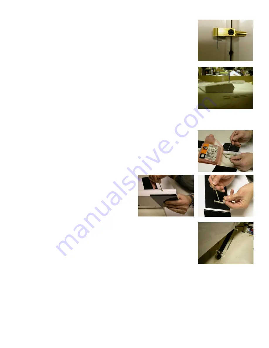
Now were going to prep the hinges for installation.  Take a small drop of oil 
and place it in each of the pivot points of your hinges.  The oil prevents 
excess epoxy from bonding the joint.   


Working with one panel and control surface at a time, apply epoxy into the 
hinge holes of the trailing edge hinge line.  
Apply epoxy to one side of the hinges and insert 
them into the holes.  Apply epoxy into the 
leading edge holes of the control surface and the 
other side of the hinges.   


Carefully insert the control surface into the 
hinges and butt the two surfaces together.  Move 
the surface up and down a couple of times to make sure all the hinges are 
aligned correctly and the desired throw is attained.  35 degrees for ailerons 
and 45 degrees for all others.  


Use some masking tape to hold the surfaces together and let cure for at least 
eight hours.  Repeat this step until all of the surfaces are epoxied in place. 


Install the tiller springs you set aside in chapter 2 to the tiller horn and tiller. 


Tip#5 Optional step.  After your epoxy has cured, it would be a good time to seal all of your hinge gaps prior 
to installing you hardware.  This can provide you with a better flying aircraft by increasing control surface 
performance and preventing possible flutter.  Clear or matching covering material can be ironed in place to 
fill any gaps on the bottom of your control surfaces.   
 
Take approximately a one-inch strip of covering the length of your surface.  Fold it in half while placing into 
the gap with the control surface fully deflected up and iron it in place.  Check to make sure you still have full 
surface travel once you have completed. 
 

Summary of Contents for Edge540 II

Page 1: ...cision aircraft as well as an outstanding 3D performer We took this fantastic aircraft and made it even better with the release of the 30 Edge540 II and III Designed with 85 sq inches more wing area while reducing the total weight has made this aircraft a true performer Whether you want an aircraft precise enough to compete in IMAC or to turn it loose for the wildest 3D maneuvers on the planet our...

Page 2: ...lation Chapter 7 Control Surface Installation Chapter 8 Hardware Installation Chapter 9 Radio and Control Surface Setup Chapter 10 Final Inspection and Pre Flight Additional items needed to complete this aircraft which are not included An engine within the recommend range and propeller 6 channel computer radio and receiver recommended Batteries and switches with regulators if using Ion batteries T...

Page 3: ...r assembly 1 Canopy 1 Carbon fiber wing tube 1 1 4 x3 1 Carbon fiber stabilizer tube inch 2 Nylon wing retention bolts 1 28 inch Carbon fiber pushrod 8 Metal pushrod ends 4 Sets of aluminum control horn assemblies Edge III 1 Rudder aluminum control horn assembly Edge III 1 20oz Du bro fuel tank Edge III 6 4 40 ball links Edge III 1 Set of additional various hardware 1 Vinyl graphics package 1 Set ...

Page 4: ...nsure a scratch free finish Place an to ensure task completion Go over you model as necessary with a covering iron to insure all joints seams and corners are sealed properly Use your iron to ensure the areas where cutouts are needed for your hardware are located and sealed down such as servos tubes and control horn mounting locations Next we ll need to cut out the covering at the locations for har...

Page 5: ...en tightening the lock nuts If over tightened it can damage the composite landing gear and cause it to fail Only tighten enough to lock the axle firmly in place and not rotate Loc tite is not recommended here as it will damage the nylon bushing Slide one wheel collar or a 3mm piece of fuel tubing to the inside of each axle This acts as a spacer preventing the wheels from moving side to side and ma...

Page 6: ...4 40 bolts in the wheel pants at the locations you ve marked Apply some white wood glue to the inner side of the four 4 40 blind nuts and install the blind nuts to the inside of the wheel pants Mount the wheel pants to the landing gear using four 4 40 bolts with spring and flat washers Use loc tite on these bolts as they are prone to severe vibration Tail wheel assembly and mounting What you will ...

Page 7: ...ine on the bottom of the rudder using the two small wood screws Tip 2 Set aside your two tiller springs we will install those later after the rudder is mounted Chapter 4 Canopy and Fuselage Hatch Place an to ensure task completion Gather the following for canopy and hatch installation Canopy Fuselage and Access Hatch 15 small wood screws Two 4 40 bolts with spring and flat washers Not Provided inc...

Page 8: ...our customers can select from a wide variety of engine choices It is nearly impossible to cover every engine installation choice in this manual but we ll cover a few Your aircraft was designed around the more popular lightweight gas 3 to 3 lbs 50cc size motors Also we have provided a canister tunnel on our Edge III for those desire quieter operation Please consult the manufacturer for the installa...

Page 9: ... using your square Draw another line parallel approximately 5mm to the right of the vertical centerline This gives us our offset centerline for 3 degrees of right thrust Using your square make sure the right side of the motor box matches the left side If not use the square to as a guide for the next measurement Now measure and draw a vertical line down the inside of the right hand side of the moto...

Page 10: ...e forward CG DA 50 users only If using the DA template provided on the last page of this manual check the measurements on the template and ensure the holes are correct Cut the paper template to the size needed to tape it to the firewall using your thrust line and offset centerline as a guide DA 50 users only Using a center punch place it in each crosshair and mark each location Drill out the four ...

Page 11: ...el tool A facemask and eye protection inch low tack masking tape Pencil or dry erase marker Some card stock paper Drill and 3 32 drill bit Always wear a mask and eye protection while cutting fiberglass Take your time while installing the cowl With care you will end up with a professional installation that will make an impression at the field Close the choke and place a piece of tape over the carbu...

Page 12: ...ts Remove the card stock strips from the fuselage and bolt the cowl in place Now we are ready to do some fine trimming We will want to cut at least an extra inch cut around any of the engine components that protrude Mark any additional areas that may require trimming to include if necessary the spark plug We also want to make sure we have at least twice the area of the cowl opening open on the bot...

Page 13: ...e oil prevents excess epoxy from bonding the joint Working with one panel and control surface at a time apply epoxy into the hinge holes of the trailing edge hinge line Apply epoxy to one side of the hinges and insert them into the holes Apply epoxy into the leading edge holes of the control surface and the other side of the hinges Carefully insert the control surface into the hinges and butt the ...

Page 14: ...g tape Some foam rubber for mounting receiver ignition module and fuel tank Install 100oz or better servos for the ailerons in the servo trays located in the bottom of the wings Install 130oz or better servos for the elevators in the servo trays located in the rear of the fuselage Install one 150oz or better servo for the rudder in the center servo tray inside the fuselage Install the aluminum con...

Page 15: ...rfaces are centered Take your ruler and measure the length of CF rod you will need to cut for each control surface Cut the four rods needed to the proper length with a mask using care not to breath any of the CF dust Take masking tape and single wrap the area to be cut We recommend using a small hand saw while rotating the rod until it falls away cleanly A Dremel tool or similar will work but it t...

Page 16: ...ill need to decide whether you want a two or three line setup With a two line setup you will need an additional T fitting in the carburetor line that connects to your fuel dot or fueling device Make sure you use Tygon fuel tubing inside the tank for the clunk as well Install the fuel tank just in front of the wing tube using zip ties or hook and latch Velcro straps Place a loop in the vent line ov...

Page 17: ...o 20 expo 30 degrees for rudder with 0 to 20 expo The recommended high rates for this aircraft are 35 degrees for ailerons with 40 to 70 expo 45 degrees for elevators with 40 to 70 expo 45 degrees for rudder with 30 to 70 expo CG Range is 5 to 6 inches Place an to ensure task completion What you will need in this chapter Completed airframe Radio Throw templates or meter Blue loc tite Cut out the t...

Page 18: ...face hardware Gently tug on each surface to make sure the hinges are properly bonded Check the four 4 40 horizontal stabilizer fasteners and ensure they re in place and secured Check all servos for mounting screws Check servo arm mounting screws and inspect that the 4 40 links have been secured with lock nuts Fill fuel tank and inspect for any leaks Check your batteries in both your aircraft and r...

Page 19: ...many years of enjoyment Thank you again for choosing BME Aircraft and look for exciting future products Additional products from BME Aircraft 30 Extra 330L New Releasing this spring 30 Edge III D 30 Yak 54 III 27 Pitts Challenger 37 Ultimate 60 90 sized Cap Maniac Mini Yak 54 Electric HOT ITEM Electric Hydroplane Electric Yak Profile A complete line of high performance laminated props New Aluminum...

Page 20: ...20 Throw Template If printing from Adobe turn off page scaling Cut out around all the dotted lines ...

Reviews: