Hardware Reference Guide
79
P
RODUCT
O
VERVIEW
Fans
The SR2024 switch has four cooling fans which, by default, are always on. You can view fan status and
temperature levels in HiveManager. The fan speeds and temperature settings are preconfigured. Make sure
the switch fans have enough space for proper cooling (see
"Mounting and Installation" on page 81
.).
Displaying Fan and Temperature Status using CLI commands:
To display the current status of the fans, enter the following command:
show system fans
To display the current system temperature, enter the following command:
show system temperature
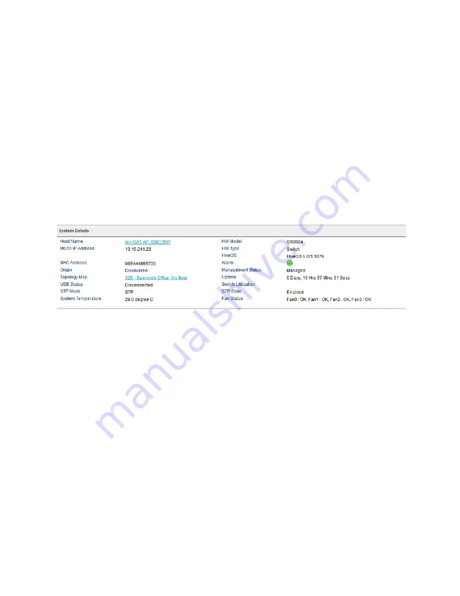
Viewing Fan and Temperature Status in HiveManager
To view fan and temperature status in HiveManager, navigate to
Monitor > Devices > Switches
. Click the
name of a switch. A page appears that shows system information for the switch. Scroll down to the
System
Details
section, where you will see information similar to that shown in
. The temperature and fan
status appear at the bottom of this section.
Figure 2 Temperature and fan information display in HiveManager
Changing the Temperature and Fan Speed Alarm Thresholds
You can change the threshold for the alarms in HiveManager. To do this, go to
Configuration > Advanced
Configuration > Management Options
. To modify existing system settings, click the name of the
management options object you want to change. In the dialog box that appears, scroll down to the
System Settings
section, where you will see the alarm fields that you can modify.
Status LEDs
The status LEDs on the SR2024 switch front panel indicate activity states by color and illumination patterns.
Press the LED mode button to cycle through Link, Stack (reserved for future use), Speed, Duplex, or PoE
modes. Depending on which mode you have selected, the port LEDs (one per port) display information
specific to the selected mode.
describes the port LED color and pattern meanings for
each mode.
SFP Port LEDs
The SFP ports LEDs are not connected to the LED mode selection button. SFP port LEDs are either
dark
(no
power to the port),
solid green
(there is an active link to the port, but no activity), or
green flashing
(port is
linked and active).
Summary of Contents for BR200-WP
Page 1: ...Aerohive Hardware Reference Guide...
Page 2: ......
Page 10: ...Contents 8 Aerohive...
Page 28: ...Chapter 2 AP121 and AP141 Platforms 26 Aerohive...
Page 42: ...Chapter 3 The AP170 Platform 40 Aerohive...
Page 74: ...Chapter 6 AP330 and AP350 Platforms 72 Aerohive...
Page 98: ...Chapter 9 BR200 and BR200 WP Routers 96 Aerohive...
Page 110: ...Chapter 11 The HiveManager Platform 108 Aerohive...
Page 124: ...Index 122 Aerohive...


