


10
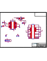
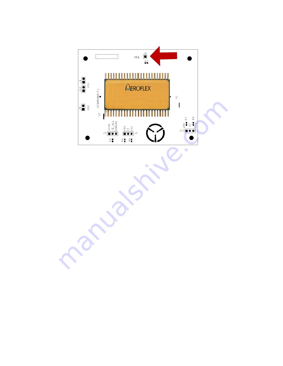
The open drain MBE pin drives low when ECC logic detects two bit errors during the current read cycle. It
allows for wired-or of multiple MBE signals when using multiple MRAMs. The MBE signal is routed to
the one pin J6 header. This pin can be monitored if the user chooses to do so.
UT8MR8M8
MBE
Figure 8. MBE pin
6.0
Quick Start Guide
The following steps describe how the user to get the UT8MR8M8-EVB up and running with the
UT699 LEON-3FT EVB.
1.
Connect J5to the UT8MR8M8-EVB to ROMSN0 for using MRAM as PROM
- or -
Connect J5to the UT8MR8M8-EVB to IOSN for using MRAM as IO Space
2.
Disconnect power to the UT699-EVB
3.
Plug the UT8MR8M8-EVB J7 to J9 on the UT699-EVB
4.
Configure DIP switches S3 and S4 as shown in Table 9 and 10.
5.
Reference Section 3 “SETTING UP AND USING THE BOARD” in the user’s manual for
the GR-UT699 board. Install the jumpers as indicated in Table 11.
Summary of Contents for UT8MR8M8-EVB
Page 5: ...5 Figure 3 Aeroflex Gaisler LEON 3FT J7 to J9 connector...
Page 16: ...16 116 VSS 117 12V NC 118 VSS 119 5V NC 120 VSS...
Page 17: ...17 8 0 BOARD SCHEMATICS The schematics are for reference ONLY...
Page 19: ...18 ORDERING INFORMATION UT Device Type 8MR8M8 EVB 64Megabit Non Volatile MRAM Evaluation Board...