


48
Aermec cod. 5806715_00 12.01
NRP 0200-0750
EN
1. Before
connec ng the unit to the power supply
mains, ensure that the disconnec on switch is
open.
2.
Open the front panel.
3.
Use the plates to pass the main electric power
supply cable and the cables of the other
external connec ons under the responsibility of
the installer.
4.
It is forbidden to access with electric cables
in posi ons not speci
fi
cally envisioned in this
manual.
5.
Avoid direct contact with non-insulated copper
piping and with the compressor.
6. Iden fy the terminals for the electric
connec on and always refer to the wiring
diagram supplied with the unit.
7.
For the func onal connec on of the unit, take
the power supply cable to the electric control
board inside the unit and connect it to terminals
L1-L2-L3 and PE respec ng the polari es.
8.
L1-L2-L3 as phases, and PE as earth; see
fi
gure.
9. Re-posi on the inspec on panels.
10. Ensure that all protec ons removed for the
electric connec on have been restored before
electrically powering the unit.
11. Posi on the system master switch (external to
the appliance) at “ON”.
27.2. PREPARATION FOR COMMISSIONING
Please note that, on request by the Aermec customer
or the legi mate owner of the machine, the units
in this series can be started up by the AERMEC
A er-Sales Service in your area (valid only on Italian
territory). The start of opera on must be scheduled in
advance based on the me frame for the comple on
of works for the system. Prior to the interven on, all
other works (electrical and hydraulic hook-ups, priming
and bleeding of air from the system) must have been
completed.
27.3. START UP
27.3.1. PRELIMINARY OPERATIONS TO BE
PERFORMED WITH NO VOLTAGE PRESENT
Control:
1.
All safety condi ons have been respected.
2.
The unit is correctly
fi
xed to the support
surface.
3.
The minimum technical spaces have been
respected.
4.
That the main power supply cables have
appropriate cross-sec on, which can support
the total absorp on of the unit. (see electric
data sec ons) and that the unit has been duly
connected to the ground.
5.
That all the electrical connec ons have been
made correctly and all the terminals adequately
ghtened.
27.3.2. THE
FOLLOWING OPERATIONS ARE TO BE
CARRIED OUT WHEN THE UNIT IS LIVE
1.
Supply power to the unit by turning the master
switch to the ON position; see (fig1.) The display
will come on a few seconds after voltage has
been supplied; check that the operating status
is on OFF.(OFF BY KEY B on lower side of the
display).
2.
Use a tester to verify that the value of the
power supply voltage to the RST phases is equal
to 400V ±10%; also verify that the unbalance
between phases is no greater than 3%.
3.
Check that the connections made by the installer
are in compliance with the documentation.
4.
Verify that the resistor of the compressor
casing is working by measuring the increase in
temperature of the oil pan. The resistance/s
must function for at least 12 hours before
start-up of the compressor and in any event,
the temperature of the oil pan must be 10-15°C
higher than room temperature.
HYDRAULIC CIRCUIT
1.
Check that all hydraulic connections are made
correctly, that the plate indications are complied
with and that a mechanical filter has been
installed at the evaporator inlet. (Mandatory
component for warranty to be valid).
2.
Make sure that the circulation pump/s is
operating and that the water flow rate is
sufficient to close the contact of the flow switch.
3.
Check the water flow rate, measuring the
pressure difference between inlet and outlet of
the evaporator and calculate the flow rate using
the evaporator pressure drop diagram present in
this documentation.
4.
Check correct functioning of the flow meters,
if installed; on closing the cut-off valve at the
outlet of the heat exchanger, the unit must
display the block. Finally, open the valve and
rearm the block.
27.4. MACHINE COMMISSIONING
After having performed all controls stated above, it
is possible to start the unit by pressing the ON key.
The display shows the temperature of the water and
machine functioning mode. Check the operating
parameters (set-point) and reset any alarms present.
After a few minutes, the unit will begin operating.
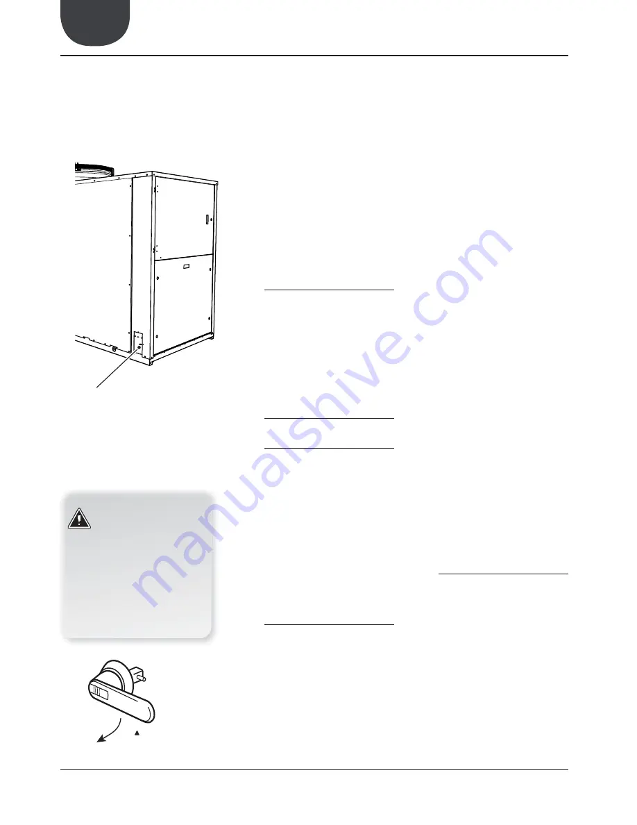
Holes for electric cables
Fig. 1
ATTENTION:
Before carrying out the controls
indicated below, make sure that the
unit is disconnected from the power
mains. Make sure that the master
switch is locked in the OFF position
and an appropriate sign is affixed.
Before starting the operations, check
that there is no voltage present using a
voltmeter or a phase indicator.
28. ELECTRIC POWER CONNECTION TO THE ELECTRICAL MAINS
29. CONTROL AND COMMISSIONING