background image

22.05 – 4037360_01

7

1  

 GENERAL  WARNINGS

 INTRODUCTION

The unit you have purchased is a complex machine. During installation, operation, 
maintenance and repair, people and property can be exposed to risks caused by 
certain conditions or components such as, but not limited to, refrigerant gas, oils, 
moving parts, pressures, sources of heat, electrical voltage.
This manual provides information about the standard functions and procedures of 
all units in the series and is an important support document for qualified personnel, 
but does not replace them.

Before proceeding with the installation and start-up of the unit, careful-

ly read this manual and all of its notes marked with the following sym-

bols, which indicate the various levels of hazard or situations that are 

potentially hazardous to prevent malfunctioning or physical damage to 

property or personal injury:

HAZARD indicates a situation of imminent danger:

 if it is not observed, 

it can cause death or serious injuries, it is mandatory to carefully follow the 
listed measures.

WARNINGS indicate a potentially dangerous situation:

 which if not 

avoided could cause serious or fatal injuries. Pay close attention while 
working

WARNING indicates a potentially dangerous situation that, if not 

avoided, could lead to slight or moderate injuries or damage to prop-

erty

INFORMATION this points out that a potentially harmful situation 

could occur that, if not avoided, could cause property damage

IMPORTANT additional information on how to use the product

The manual contains important indications for commissioning the unit as well as 
fundamental instructions in order to prevent personal injuries or damage to the 
machine during its operation. Finally, to also guarantee that it will operate perfectly, 
maintenance instructions are provided.
The unit must be installed by specialised technicians in compliance with current 
laws in the country of installation. The unit must also be started up by authorised 
and trained personnel, and all activities must be carried out in compliance with and 
in observance of all the local standards and laws, and all work on the system must 
be performed in a workmanlike manner.

Even though our unit is equipped with numerous safety and protec-

tion devices and has been tested in the factory, maximum attention 

must be paid when working on it, observing the precautions against 

residual risks.

 GENERAL  WARNINGS

ATTENTION:

—  The machine must be transported in compliance with the laws in force in the 

country of destination, considering the characteristics of the fluids it contains 
and their characterisation. Incorrect transport could cause machine damage, 
which would also generate refrigerant leaks. Before the first start-up, it is neces-
sary to search for any leaks using suitable personal protective equipment;

—  When the product is received, check the condition and completeness of the 

supply and, if it does not match what was ordered, contact the agency that sold 
the equipment;

—  The product is intended to be used for the purpose indicated by Aermec and for 

which it was expressly designed. Aermec shall not be contractually or non-con-
tractually liable for any damage to people, animals or objects, installation, ad-
justment and maintenance errors or incorrect use;

—  During installation and/or maintenance operations, remember that they must 

be performed by qualified and prepared personnel and it is require to wear 
protective devices (gloves, eye protection, helmet, …) that are suitable for the 
operations to be performed: do not wear clothing or accessories that can get 
caught or be sucked in by the air flows; collect and tie up hair before accessing 
the inside of the unit, Aermec shall not be held liable for the failure to observe 
the safety and accident prevention regulations in force;


Personal protective 

equipment (PPE) 

(1)

Operations

Handling

Installation and/or 

maintenance

Welding or brazing

Safety gloves, 
helmet, goggles, 
safety footwear, 
protective garments.

Earmuffs

(1) It is recommended to follow the instructions in EN 378-3.

—  Observe the laws in force in the country of unit installation that concern use and 

disposal of the packaging, the products used for cleaning and maintenance, 
and for managing the end of the unit's service life;

—  Repair and maintenance work must be performed by Aermec Technical Service. 

Do not modify or tamper with the unit as dangerous situations may be created 
and the equipment manufacturer will not be liable for any damage caused;

—  In the case of abnormal operation, or if liquids leak, move the main switch for 

the system to "off" and close the interception taps. Call the local AermecTechni-
cal Service and do not work on the equipment personally;

—  The unit must be installed in structures that are protected against atmospheric 

discharges, as required by applicable laws and technical standards;

—  The equipment contain refrigerant gas: proceed carefully to prevent damaging 

the gas circuit or the finned coil;

—  Based on EU regulation 517/2014 concerning certain fluorinated greenhouse 

gases, it is mandatory to indicate the total quantity of refrigerant contained in 
the installed system. This value is indicated on the rating plate on the unit;

—  This unit contains fluorinated greenhouse gases covered by the Kyoto Proto-

col. Maintenance and disposal operations must be only carried out by qualified 
personnel;

—  This manual is an integral part of the unit and as a result it must be stored care-

fully and must always accompany it, even if transferred to another owner or 
user, or if transferred to another plant. If damaged or lost, a copy can be down-
loaded from our website www.aermec.com

—  The overall fire risk assessment at the place of installation (i.e. fire load calcula-

tion) is the responsibility of the user.

—  Perform the plant connections following the indications provided in this man-

ual.

IT IS FORBIDDEN TO:

—  It is not permitted to walk on the machine or to place other items on it: no part 

of the unit may be used as a walkway or support for goods or people. Periodical-
ly check and repair or, if necessary, replace any component or pipe that shows 
signs of damage. Use a platform, or suitable scaffolding to work at higher levels;

—  Remove the protections from mobile elements while the unit is running;
—  Touch the moving parts, stand between them or insert pointed objects through 

the grids.

—  Any technical intervention or cleaning operation before having disconnected 

the appliance from the mains electric power supply: by positioning the system 
master switch and the main device switch at "OFF".

—  Modify the safety or regulation devices. The devices must be replaced by the 

After-sales Technical Service Aermec, using only original components.

—  Pull, detach or twist the electrical cables coming out of the unit even if it is dis-

connected from the mains electric power supply;

—  To dispose of the packaging material in the environment or leave it within reach 

of children: as it may be a potential source of danger. Therefore it must be dis-
posed of according to what is defined by current laws.

 ESSENTIAL SAFETY RULES

Any technical intervention must be performed by qualified and author-

ised personnel. The personnel performing the work must have been 

trained and be familiar with this type of product and its installation.

The machine must only be employed for the use for which it was made; any other 
use can be dangerous and void the warranty;

It is not permitted to walk on the machine or to place other items on it. No part 
of the unit may be used as a walkway or support for goods or people. Periodically 

Summary of Contents for NLC 0280

Page 1: ...4 0 3 7 3 6 0 _ 0 1 T r a n s l a t i o n o f O r i g i n a l i n s t r u c t i o n s w w w a e r m e c c o m Installation Manual NLC 0280 1250 AIR WATER CHILLER C o o l i n g c a p a c i t y 1 4 5 8 7 2 t o n ...

Page 2: ......

Page 3: ...nt to present the product and help you select the unit that best meets the needs of your system However please note that for a more accurate selection you can also use the Magellano selection program available on our website Aermec Aermec always attentive to the continuous changes in the market and its regulations reserves the right to make all the changes deemed necessary for improving the produc...

Page 4: ... Equipment WEEE please return the device using appropriate collection systems or contact the retailer where the product was purchased Please contact your local authority for further details Illegal dumping of the product by the user entails the application of administrative sanctions provided by law All specifications are subject to change without prior notice Although every effort has been made t...

Page 5: ... Weight distribution and centres of gravity during operation p 31 Antivibration p 32 11 Weights p 32 12 Dimensional tables p 33 0280 0300 0330 0350 00 p 33 0280 0300 0330 0350 P1 P2 P3 P4 p 34 0550 0600 0650 0675 00 p 35 0550 0600 0650 0675 P1 P2 P3 P4 p 36 0750 00 p 37 0800 0900 1000 1100 1250 01 02 03 04 p 38 13 Hydraulic connections p 39 0280 0300 0330 0350 00 p 39 0280 0300 0330 0350 P1 P2 P3 ...

Page 6: ...6 22 05 4037360_01 Interventions on the circuit p 54 22 Configurator p 55 23 Accessories p 56 Factory fitted accessories p 56 Accessories compatibility p 56 ...

Page 7: ...ec shall not be held liable for the failure to observe the safety and accident prevention regulations in force Personal protective equipment PPE 1 Operations Handling Installation and or maintenance Welding or brazing Safety gloves helmet goggles safety footwear protective garments Earmuffs 1 It is recommended to follow the instructions in EN 378 3 Observe the laws in force in the country of unit ...

Page 8: ...res on elec trical equipment and for lubricant oil of the compressor and the refrigerant The unit contains pressurised refrigerant gas no operation may be performed on pressurised equipment except during maintenance which must be per formed by skilled and qualified personnel Perform brazing or welding only on empty pipes and clear of any lubricating oil residues do not near flames or other heat so...

Page 9: ... poses a serious risk The combined effects of the salt loaded mist and in dustrial emissions accelerate corrosion Within the manufacturing plants corrosive gas may result from the processing of chemicals or by the typical industrial processes used in manufacturing Potential sources of risk to be considered are open sewage systems exhaust vents diesel engine exhaust emissions from heavy traffic lan...

Page 10: ...e adequate ventilation Don t place or storage the refrigerating system in confined spaces Avoid traps where gases may fall and stagnate Avoid open flames and ignition sources near the refrigerant system INSTALLATION REQUIREMENTS In particular the unit is intended to be connected to a hydronic system that must be designed to be classified according to EN 378 1 as an indirect ventilated system ref E...

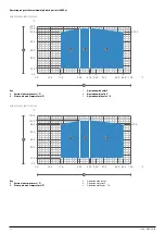
Page 11: ...ctions It should be installed if wind speed is above 4 9 knot POWER SUPPLY 460V 575V Operating range at the maximum outside air temperature 0280 0300 0330 0350 0550 0600 0650 0750 0800 0900 1000 1100 Key A External air temperature F B Water produced temperature F 1 Operation with valve Y 2 Operation witj valve Z 3 Operation witjh valve X B A 1 2 3 F F 0 0 14 0 40 0 60 0 80 0 105 0 105 8 114 8 120 ...

Page 12: ...ve Z 3 Operation witjh valve X B A 1 2 3 F F 0 0 14 0 40 0 60 0 80 0 105 0 105 8 114 8 120 0 0 0 10 0 17 6 32 0 39 2 44 0 50 0 60 0 64 4 70 0 0300 0330 0350 0650 0750 1100 Key A External air temperature F B Water produced temperature F 1 Operation with valve Y 2 Operation witj valve Z 3 Operation witjh valve X B A 1 2 3 F F 0 0 14 0 40 0 60 0 80 0 97 6 98 5 107 5 120 0 0 0 10 0 17 6 32 0 39 2 44 0...

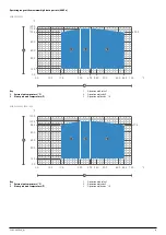
Page 13: ...20 0 0 0 10 0 17 6 32 0 39 2 44 0 50 0 60 0 64 4 70 0 POWER SUPPLY 230V Operating range at the maximum outside air temperature 0280 0300 0330 0550 0600 0650 0800 0900 1000 1100 Key A External air temperature F B Water produced temperature F 1 Operation with valve Y 2 Operation witj valve Z 3 Operation witjh valve X B A 1 2 3 F F 0 0 14 0 40 0 60 0 80 0 105 0 105 8 114 8 120 0 0 0 10 0 17 6 32 0 39...

Page 14: ...B A 1 2 3 F F 0 0 14 0 40 0 60 0 80 0 103 2 104 0 113 0 120 0 0 0 10 0 17 6 32 0 39 2 44 0 50 0 60 0 64 4 70 0 0675 1250 Key A External air temperature F B Water produced temperature F 1 Operation with valve Y 2 Operation witj valve Z 3 Operation witjh valve X B A 1 2 3 F F 0 0 14 0 40 0 60 0 80 0 101 4 102 2 111 2 120 0 0 0 10 0 17 6 32 0 39 2 44 0 50 0 60 0 64 4 70 0 ...

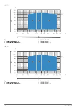
Page 15: ...ration witjh valve X B A 1 2 3 F F 0 0 14 0 40 0 60 0 80 0 105 0 105 8 114 8 120 0 0 0 10 0 17 6 32 0 39 2 44 0 50 0 60 0 64 4 70 0 0300 0330 0600 0650 0900 1000 1100 Key A External air temperature F B Water produced temperature F 1 Operation with valve Y 2 Operation witj valve Z 3 Operation witjh valve X B A 1 2 3 F F 0 0 14 0 40 0 60 0 80 0 97 6 98 5 107 5 120 0 0 0 10 0 17 6 32 0 39 2 44 0 50 0...

Page 16: ...X B A 1 2 3 F F 0 0 14 0 40 0 60 0 80 0 95 8 96 7 105 7 120 0 0 0 10 0 17 6 32 0 39 2 44 0 50 0 60 0 64 4 70 0 0675 1250 Key A External air temperature F B Water produced temperature F 1 Operation with valve Y 2 Operation witj valve Z 3 Operation witjh valve X B A 1 2 3 F F 0 0 14 0 40 0 60 0 80 0 94 0 94 9 103 9 120 0 0 0 10 0 17 6 32 0 39 2 44 0 50 0 60 0 64 4 70 0 ...

Page 17: ... 2 Operation witj valve Z 3 Operation witjh valve X B A 1 2 3 F F 0 0 14 0 40 0 60 0 80 0 105 0 105 8 114 8 120 0 0 0 10 0 17 6 32 0 39 2 44 0 50 0 60 0 64 4 70 0 0350 0750 Key A External air temperature F B Water produced temperature F 1 Operation with valve Y 2 Operation witj valve Z 3 Operation witjh valve X B A 1 2 3 F F 0 0 14 0 40 0 60 0 80 0 103 2 104 0 113 0 120 0 0 0 10 0 17 6 32 0 39 2 4...

Page 18: ...X B A 1 2 3 F F 0 0 14 0 40 0 60 0 80 0 97 8 98 6 107 6 120 0 0 0 10 0 17 6 32 0 39 2 44 0 50 0 60 0 64 4 70 0 0675 1250 Key A External air temperature F B Water produced temperature F 1 Operation with valve Y 2 Operation witj valve Z 3 Operation witjh valve X B A 1 2 3 F F 0 0 14 0 40 0 60 0 80 0 94 2 95 0 104 0 120 0 0 0 10 0 17 6 32 0 39 2 44 0 50 0 60 0 64 4 70 0 ...

Page 19: ...3 Operation witjh valve X B A 1 2 3 F F 0 0 14 0 40 0 60 0 80 0 105 0 105 8 114 8 120 0 0 0 10 0 17 6 32 0 39 2 44 0 50 0 60 0 64 4 70 0 0300 0330 0600 0900 1000 Key A External air temperature F B Water produced temperature F 1 Operation with valve Y 2 Operation witj valve Z 3 Operation witjh valve X B A 1 2 3 F F 0 0 14 0 40 0 60 0 80 0 97 6 98 5 107 5 120 0 0 0 10 0 17 6 32 0 39 2 44 0 50 0 60 0...

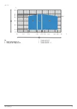
Page 20: ...X B A 1 2 3 F F 0 0 14 0 40 0 60 0 80 0 95 8 96 7 105 7 120 0 0 0 10 0 17 6 32 0 39 2 44 0 50 0 60 0 64 4 70 0 0650 1100 Key A External air temperature F B Water produced temperature F 1 Operation with valve Y 2 Operation witj valve Z 3 Operation witjh valve X B A 1 2 3 F F 0 0 14 0 40 0 60 0 80 0 90 4 91 3 100 3 120 0 0 0 10 0 17 6 32 0 39 2 44 0 50 0 60 0 64 4 70 0 ...

Page 21: ...ternal air temperature F B Water produced temperature F 1 Operation with valve Y 2 Operation witj valve Z 3 Operation witjh valve X B A 1 2 3 F F 0 0 14 0 40 0 60 0 80 0 86 8 87 7 96 7 120 0 0 0 10 0 17 6 32 0 39 2 44 0 50 0 60 0 64 4 70 0 ...

Page 22: ...er drier 16 Electronic thermostatic ex pansion valve 1 2 3 4 5 5 6 7 8 9 9 10 11 12 13 13 14 15 15 16 NLC 0750 1250 A 1 Fan Plug fan 2 Charging connection 3 Finned coil 4 Isolation valve 5 Pressure relief valve 6 High pressure transducer 7 High pressure switch 8 Discharge temperature sensor 9 Compressor 10 Low pressure transducer 11 Plate heat exchanger 12 Mechanic thermostatic valve 13 Sight glas...

Page 23: ...ate 3 Packaging label When the unit is positioned make sure that the rating plate is well visible as the information provided on it is essential for correct maintenance PACKAGING HANDLING AND REMOVAL Before carrying out the packaging removal or transport operations put on personal protective equipment and use devices and instruments suitable for the dimensions and weigh of the equipment All handli...

Page 24: ...rely technical requirements as well as any local laws in force For unit installation it is important to perform the following preliminary prepara tion tasks The following must be avoided Locations with aggressive atmospheres Areas in which the unit s noise level could be amplified due to reverberations or resonance POSITIONING The units must They must be installed in an area that cannot be accesse...

Page 25: ... must have space to allow all routine and extraordinary maintenance to be performed C1 C2 B1 B2 A1 Size 0280 0300 0330 0350 0550 0600 0650 0675 0750 0800 0900 1000 1100 1250 Minimumtechnicalspaces A1 A in 39 4 39 4 39 4 39 4 39 4 39 4 39 4 39 4 39 4 39 4 39 4 39 4 39 4 39 4 B1 A in 39 4 39 4 39 4 39 4 39 4 39 4 39 4 39 4 39 4 39 4 39 4 39 4 39 4 39 4 B2 A in 19 7 19 7 19 7 19 7 19 7 19 7 19 7 19 7...

Page 26: ...pplied from the fan to the in stantaneous drop of pressure in the tube When the machine is started for the first time the installer should set from the control panel the number of revs of the fan capable of providing head equal to the total pressure drops of the piping The number of fan revs is generally less than the maximum number of revs the fan is capable of 0 10 The number of revs is set indi...

Page 27: ...22 05 4037360_01 27 WARNING The weight of the piping must not be borne by the appliance Example of ductwork ...

Page 28: ...9 POSITION OF THE VIBRATION DAMPERS X Y G 1 2 3 4 1 2 3 4 XG Y G 1 2 3 4 5 6 XG Y G 1 2 3 4 XG Y G 1 2 3 4 5 6 XG Y G NLC 0280 0350 A NLC 0550 0675 A Vers 00 Vers P1 P4 Vers 00 P1 P4 Vers 01 04 Vers 01 04 Top view Top view ...

Page 29: ...05 4037360_01 29 NLC 0750 A Vers 00 P1 P4 Vers 01 04 NLC 0800 1250 A Vers 00 P1 P4 Vers 01 04 1 2 3 4 5 6 XG Y G 1 2 3 4 5 6 7 8 XG Y G 1 2 3 4 5 6 7 8 XG Y G XG Y G 1 2 3 4 5 6 7 8 9 10 Top view Top view ...

Page 30: ...ntreofgravity empty X A in 58 8 57 3 56 9 56 7 72 9 69 4 69 1 67 7 106 3 135 6 136 9 131 9 130 8 129 3 Y A in 18 7 18 3 18 6 18 5 21 3 21 2 21 0 20 9 21 7 22 0 21 9 21 8 21 9 21 7 Weightdistributionin onthesupports empty 1 A 16 16 17 17 20 21 21 21 11 12 12 13 13 13 2 A 12 13 13 13 20 22 22 23 11 12 11 13 13 13 3 A 28 27 28 28 27 27 27 26 20 11 10 10 10 10 4 A 22 22 21 21 28 28 28 28 20 11 10 10 1...

Page 31: ...2 11 11 11 7 A 13 12 12 12 12 11 8 A 13 12 12 12 11 11 9 A 10 10 9 9 8 10 A 10 9 9 8 8 INTEGRATED HYDRONIC KIT 02 04 Centreofgravity duringoperation X A in 72 2 70 7 70 1 69 9 91 1 87 1 86 3 84 9 126 6 157 2 157 3 152 2 150 5 148 7 Y A in 21 1 20 7 20 9 20 9 21 5 21 4 21 2 26 0 21 8 22 0 21 9 21 8 21 9 21 7 Weightdistributionin onthesupports duringoperation 1 A 13 14 14 14 15 16 16 17 10 11 10 11 ...

Page 32: ... WEIGHTS Size 0280 0300 0330 0350 0550 0600 0650 0675 0750 0800 0900 1000 1100 1250 INTEGRATED HYDRONIC KIT 00 Weights Emptyweight A lbs 1 700 1 803 1 854 1 870 2 945 3 305 3 428 3 413 4 460 5 465 5 838 6 204 6 508 6 717 Weightfunctioning A lbs 1 713 1 821 1 870 1 887 2 974 3 336 3 463 3 448 4 508 5 520 5 900 6 272 6 576 6 786 INTEGRATED HYDRONIC KIT 01 03 Weights Emptyweight A lbs 2 421 2 524 2 5...

Page 33: ... 44 3 11 9 2 0 6 9 6 9 6 8 6 8 26 7 26 7 26 7 26 7 2 0 11 9 71 9 A B C Size 0280 0300 0330 0350 INTEGRATED HYDRONIC KIT 00 01 02 03 04 P1 P2 P3 P4 Dimensionsandweightsfortransport A A in Contactthe factory Contactthe factory Contactthe factory Contactthe factory B A in Contactthe factory Contactthe factory Contactthe factory Contactthe factory C A in Contactthe factory Contactthe factory Contactth...

Page 34: ... 4 9 1 6 43 3 1 2 10 1 2 0 11 9 71 9 3 0 6 8 6 8 26 7 26 7 A B C Size 0280 0300 0330 0350 INTEGRATED HYDRONIC KIT 00 01 02 03 04 P1 P2 P3 P4 Dimensionsandweightsfortransport A A in Contactthe factory Contactthe factory Contactthe factory Contactthe factory B A in Contactthe factory Contactthe factory Contactthe factory Contactthe factory C A in Contactthe factory Contactthe factory Contactthe fact...

Page 35: ...6 8 26 7 1 9 1 9 30 0 30 2 29 6 11 9 2 0 26 7 26 7 26 7 6 8 26 7 3 5 3 5 1 9 1 9 A B C Size 0550 0600 0650 0675 INTEGRATED HYDRONIC KIT 00 01 02 03 04 P1 P2 P3 P4 Dimensionsandweightsfortransport A A in 93 4 93 4 93 4 93 4 B A in 62 2 62 2 62 2 62 2 C A in 137 6 137 6 137 6 137 6 For the sizes shown in the table the transportation dimensions refer to the acces sory CRATE 22 ...

Page 36: ...29 6 11 9 2 0 3 5 3 5 1 9 1 9 26 7 6 8 26 7 26 7 26 7 A B C Size 0550 0600 0650 0675 INTEGRATED HYDRONIC KIT 00 01 02 03 04 P1 P2 P3 P4 Dimensionsandweightsfortransport A A in 93 4 93 4 93 4 93 4 B A in 62 2 62 2 62 2 62 2 C A in 137 6 137 6 137 6 137 6 For the sizes shown in the table the transportation dimensions refer to the acces sory CRATE 22 ...

Page 37: ...93 1 11 9 2 0 6 8 26 7 26 7 10 2 26 7 26 7 26 7 3 5 26 7 6 8 1 9 1 9 1 9 3 5 4 0 3 3 2 1 7 9 26 7 26 7 26 7 26 7 26 7 26 7 6 8 1 9 11 9 71 9 10 2 6 8 1 9 1 9 1 9 56 5 56 5 63 0 A B C Size 0750 INTEGRATED HYDRONIC KIT 00 01 02 03 04 P1 P2 P3 P4 Dimensionsandweightsfortransport A A in Contactthefactory B A in Contactthefactory C A in Contactthefactory ...

Page 38: ... 5 26 7 26 7 26 7 26 7 26 7 26 7 26 7 6 8 6 8 6 8 2 0 3 5 3 3 3 4 8 0 A B C Size 0800 0900 1000 1100 1250 INTEGRATED HYDRONIC KIT 00 01 02 03 04 P1 P2 P3 P4 Dimensionsandweightsfortransport A A in Contactthe factory Contactthe factory Contactthe factory Contactthe factory Contactthe factory B A in Contactthe factory Contactthe factory Contactthe factory Contactthe factory Contactthe factory C A in...

Page 39: ... 0330 0350 00 13 1 9 9 25 8 18 5 8 6 6 2 Evaporator grooved joints Ø 2 Desuperheater grooved joints Ø 1 1 2 0280 0300 0330 0350 P1 P2 P3 P4 5 7 6 5 40 3 9 5 5 6 15 1 Evaporator grooved joints Ø 2 Pump grooved joints Ø 2 Desuperheater grooved joints Ø 1 1 2 ...

Page 40: ...t EU Grooved joint US Grooved nipple US Reduction adapter EU US 0550 0600 0650 0675 00 5 6 11 9 5 6 3 1 9 5 24 1 49 8 6 5 11 9 15 8 85 7 71 9 1 9 1 9 0 8 Evaporator grooved joints Ø 2 1 2 EU Desuperheater grooved joints Ø 1 1 2 0550 0600 0650 0675 P1 P2 P3 P4 11 9 1 9 11 9 87 2 71 9 1 9 20 6 5 7 9 5 49 8 6 5 14 9 Pump grooved joints Ø 2 1 2 EU Evaporator grooved joints Ø 2 1 2 EU Desuperheater gro...

Page 41: ...orator grooved joints Ø 2 1 2 Desuperheater grooved joints Ø 1 1 2 0800 0900 1000 1100 1250 01 02 03 04 12 3 1 7 1 7 12 3 6 5 49 8 24 1 9 5 6 1 3 1 5 6 43 3 5 6 Evaporator grooved joints Ø 3 Storage tank grooved joints Ø 3 Desuperheater grooved joints Ø 1 1 2 ...

Page 42: ...e online at www aermec com It is important to follow the recommendations not complete below The water pipes must not transmit radial or axial forces or vibrations to the ex changers use flexible hoses to reduce the transmitted vibrations It is necessary to install manual or automatic vent valves in the highest points of the circuit and also provide discharge fittings in the lowest points to allow ...

Page 43: ...inimum temperature provided for a given installation Take the necessary precautions if using non passivated anti freeze solu tions monoethylene glycol or monopropylene glycol Corrosion phenom ena may occur with these anti freeze solutions in contact with oxygen However always refer to the glycol supplier documentation to check its recom mended concentration IT IS FORBIDDEN to insert glycol in the ...

Page 44: ...eriod for heat pumps MAXIMUM SYSTEM WATER CONTENT Units with the hydronic kit mounted come standard with the expansion vessel set at 21 8 psi the pressure relief valve and the water filter mounted The maximum system water content depends on the capacity of the expansion vessel and on the calibration of the pressure relief valve Size 0280 0300 0330 0350 0550 0600 0650 0675 0750 0800 0900 1000 1100 ...

Page 45: ... figure according to the formula p rating bar H ft 33 5 1 0 For example if level difference H is equal to 65 6 ft the calibration value of the vessel will be 33 4 psi If the calibration value obtained from the formula is less than 21 8 psi i e for H 40 2 use the standard calibration Key A Expansion vessel 1 Check that highest installation is not higher than 180 4 ft 2 Ensure that lowest utility ca...

Page 46: ...t off valves 1 2 2 9 9 16 3 5 7 6 8 11 13 15 12 5 10 10 14 4 Water characteristics System Chiller with plate heat exchanger PH 7 5 9 Total hardness 4 5 8 5 dH Temperature 65 C Oxygen content 0 1 ppm Max glycol amount 50 Phosphates PO 2ppm Manganese Mn 0 05 ppm Iron Fe 0 3 ppm Alkalinity HCO 70 300 ppm Chloride ions Cl 50 ppm Sulphate ions SO 50 ppm Sulphide ion S None Ammonium ions NH None Silica ...

Page 47: ... 13 18 12 6 9 8 10 11 8 15 15 16 7 P1 P3 5 P2 P4 17 5 5 Water characteristics System Chiller with plate heat exchanger PH 7 5 9 Total hardness 4 5 8 5 dH Temperature 65 C Oxygen content 0 1 ppm Max glycol amount 50 Phosphates PO 2ppm Manganese Mn 0 05 ppm Iron Fe 0 3 ppm Alkalinity HCO 70 300 ppm Chloride ions Cl 50 ppm Sulphate ions SO 50 ppm Sulphide ion S None Ammonium ions NH None Silica SiO 3...

Page 48: ...P4 9 5 5 Water characteristics System Chiller with plate heat exchanger PH 7 5 9 Total hardness 4 5 8 5 dH Temperature 65 C Oxygen content 0 1 ppm Max glycol amount 50 Phosphates PO 2ppm Manganese Mn 0 05 ppm Iron Fe 0 3 ppm Alkalinity HCO 70 300 ppm Chloride ions Cl 50 ppm Sulphate ions SO 50 ppm Sulphide ion S None Ammonium ions NH None Silica SiO 30 ppm It is of fundamental importance to keep t...

Page 49: ... design electric installations following international regulations and the national regulations of the country in which the unit is installed in compliance with the legislative regulations in force at the moment of installation it is mandatory to check the machine sealing before connecting the electrical wiring The machine must only be powered once the hydraulic and electric op erations are comple...

Page 50: ... for the electric connection and always refer exclusively to the wiring diagram supplied with the unit Remove any protections from the cable fixing points For the functional connection of the unit take the power supply cable to the electric control board inside the unit and connect it to clamps L1 L2 L3 and PE respecting the polarities L1 L2 L3 as phases and PE as grounding Ensure that all protect...

Page 51: ...talled in each inlet heat exchanger Mandatory component for warranty to be valid Check that the circulation pump s are working and that the wa ter flow rate is sufficient to close the flow switch contact if installed We recommend installing one always upstream of every heat exchanger Check the water flow rate measuring the pressure difference between inlet and outlet of the evaporator and calculat...

Page 52: ... stop and take appropriate precautions to prevent their activation before accessing them If the unit has components such as integrated inverters disconnect the power supply and wait at least 15 minutes before accessing it for maintenance opera tions the internal components remain energised for this period generating the risk of electrocution Isolate the unit from the mains by means of the external...

Page 53: ...e compressor inputs and outputs ther mometers connected to thermocouple probes that are fastened to the pipes at the compressor inputs and outputs Do not use metratasts as they require the operator to approach the machine s cooling circuit Turn on the machine and acquire the measurements remaining at a distance and in a position not exposed to the pressurised parts of the cooling circuit As soon a...

Page 54: ...clean the coils refer to the dedicated chapter INTERVENTIONS ON THE CIRCUIT DESCRIPTION FREQUENCY Note 3Mths 6Mths 12Mths INTERVENTIONSONTHECOOLINGCIRCUITOPERATINGWITHFULLLOAD Measurementoftheoverheatingtemperature Measurementoftheundercoolingtemperature Measurementoftheexhaustgastemperature Measurementoffaninput Measurementofcompressorinput COMPRESSORCONTROLS Oillevelcontrol Oilaciditycontrol Con...

Page 55: ...t circuit breakers 8 575V 3 60Hz with magnet circuit breakers 9 208V 3 60Hz with magnet circuit breakers 15 16 Integrated hydronic kit 00 Without hydronic kit Kitwithstoragetankandpump s 01 Storage tank with low head pump 02 Storage tank with low head pump stand by pump 03 Storage tank with high head pump 04 Storage tank with high head pump stand by pump Kitwithpump s P1 Single pump low head P2 Pu...

Page 56: ...ILITY Model Ver 0280 0300 0330 0350 0550 0600 0650 0675 0750 0800 0900 1000 1100 1250 AER485P1 A AERBACP A AERNET A FL UL 1 A MULTICHILLER_EVO A PGD1 A 1 Compliant with UL regulation Antivibration Ver 0280 0300 0330 0350 0550 0600 0650 Integratedhydronickit 00 A VT17 VT17 VT17 VT17 Integratedhydronickit 01 02 03 04 A VT11 VT11 VT11 VT11 Integratedhydronickit P1 P2 P3 P4 A VT13 VT13 VT13 VT13 The a...

Page 57: ...000 1100 1250 A DRE 1 DRE 1 DRE 1 DRE 1 DRE 1 DRE 1 DRE 1 1 Contact the factory A grey background indicates the accessory must be assembled in the factory Power factor correction Ver 0280 0300 0330 0350 0550 0600 0650 A RIF 1 RIF 1 RIF 1 RIF 1 RIF 1 RIF 1 RIF 1 1 Contact the factory A grey background indicates the accessory must be assembled in the factory Ver 0675 0750 0800 0900 1000 1100 1250 A ...

Page 58: ......

Page 59: ......

Page 60: ...e v i l a c q u a V R I t a l y P h o n e 3 9 0 4 4 2 6 3 3 1 1 1 F a x 3 9 0 4 4 2 9 3 5 7 7 s a l e s a e r m e c c o m w w w a e r m e c c o m 2 2 0 5 4 0 3 7 3 6 0 _ 0 1 4037360_01 DOWNLOAD THE LATEST VERSION http www aermec com qrcode asp q 18383 ...

Reviews: