


17
10. CHECKING AND FIRST START
Check before:
•
Check to make sure that the inlet and
outlet are not obstructed by objects on
both drives, external and internal.
•
Check to make sure that the cable groun-
ding is connected and not damaged.
•
Check to make sure the air filter is clean.
•
Make sure the remote control batteries
are not dead.
•
Make sure that the indoor and outdoor
units are not damaged and are securely
fastened.
All indoor units are set by default as SLAVE units, ho-
wever, because the system can work is necessary
that the system has a unit (and not more than one)
MASTER unit, otherwise the display of the indoor
unit and / or the panel flush possibly connected to
each unit’s internal system, it appears by the alarm
code L7, which just indicates that the system was
not set any master.
Documentation panel flush and the remote con-
trol, it is the procedure to set a master unit, but the
following is the procedure to do this with the remo-
te control:
1.
Get in ventilation mode only;
2.
Set the setpoint to 30 ° C;
3.
Within 5 seconds, simultaneously press the
down arrow and up arrow to 3 times;
If the operation is successful, the display will show
the acronym of uni ty internal UC, indicating that
the unit has been set as the master;
11. MAINTENANCE
11.1. ORDINARY MAINTENANCE
•
Disconnect
the power supply before
cleaning the unit
•
Disconnect
the power supply when the air
conditioner is off
•
Do not pour water directly to the unit may
cause an electrical shock
•
Clean
the cabinet with a soft, dry cloth or
a cloth slightly dampened with water or
detergent (do not use solvents)
NOTES CLEANING FILTER:
•
Do not clean with hot water.
•
Do not dry the flame.
•
Do not operate the air conditioner without
the air filter.
•
Do not use brushes or tools drives.
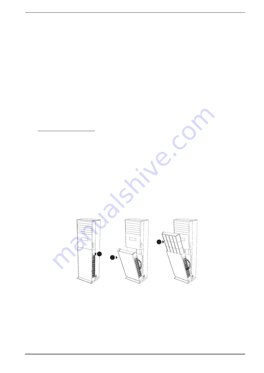
Cleaning the air filter:
Remove the air filter (as shown in the following
figures):
1. Unscrew the screw on the air intake side.
2. extract the lower part of the body con-
taining the filter.
3. Remove the filter upwards.
4. Cleaning the air filter:
•
Use a vacuum cleaner
•
If heavily soiled, use a mild detergent and
water
5. Dry the filter by exposing it to direct sun-
light
6. Replace the filter when it is dry
7. Reinstall the air filter:
•
Replace the filters.
•
Close the panel.
Maintenance after use:
•
Disconnect the power supply.
•
Clean the filter and the indoor unit.
•
Clean the outdoor unit and remove any
obstructions from the battery.
•
Restore and repaint any rusty surfaces on
the outdoor unit.
1
2
3
Summary of Contents for MVA
Page 1: ...USE AND INSTALLATION MANUAL EN MVA 1000V 1400V 5389861_02 ...
Page 25: ......
Page 26: ......
Page 27: ......