2 1 . 0 7 – 5 1 4 6 8 0 1 _ 0 0
T r a n s l a t i o n o f O r i g i n a l i n s t r u c t i o n s
w w w . a e r m e c . c o m
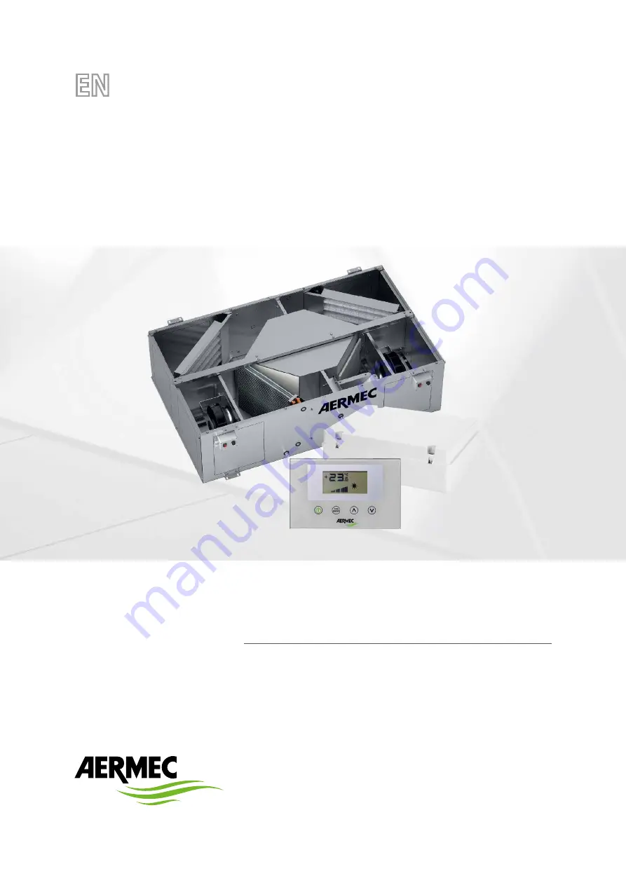
Accessory manual
HRC
CONTROL SYSTEM FOR RPLI RECOVERY UNITS
Page 1: ...2 1 0 7 5 1 4 6 8 0 1 _ 0 0 T r a n s l a t i o n o f O r i g i n a l i n s t r u c t i o n s w w w a e r m e c c o m Accessory manual HRC CONTROL SYSTEM FOR RPLI RECOVERY UNITS ...
Page 2: ... for further details Illegal dumping of the product by the user entails the application of administrative sanctions provided by law Dear customer Thank you for choosing an Aermec product It is the fruit of many years of experience and special design studies and has been made of the highest grade materials and with cutting edge technology In addition all our products bear the CE mark indicating tha...
Page 3: ...Mode p 10 Manual Mode p 10 Aux Mode p 10 4 Control logic p 11 Anti freeze through flow rate modulation p 11 Anti freeze through electric resistance p 12 Freecooling p 12 Steriliser lamp p 13 Post treatment resistance p 13 Post treatment coil p 15 5 Interface use p 17 Hardware structure p 17 Software structure p 17 Main page p 18 Input fan power page p 19 Expulsion fan power page p 19 Password page...
Page 4: ...sistive load control to treat inflow air 1 1 HRC KIT CONTENT The accessory consists of a 300x380x120 mm plastic electric control board which ensures IP56 protection and so must be installed outside the recovery unit The HRC accessory contains all the components necessary for managing the heat recovery units Electronic control board of the loads inserted in an IP56 protection rating plastic board N...
Page 5: ...oltage 230Vac 5Acurrent M7 Y2 outputforelectricpost heatingresistancecontrol secondstage Voltage 230Vac 5Acurrent M8 Y1 outputforpreheatingresistancecontrol Voltage 230Vac 5Acurrent M9 Neutralreference Voltage 230Vac 10Acurrent M10 Neutralreference Voltage 230Vac 10Acurrent M11 V3 outputforpurificationdeviceoroutputdampercontrol Voltage 230Vac 5Acurrent M12 V2 outputforVSLvalvecontrol coolingonly ...
Page 6: ...atusforcinginput M26 RS485 serial inputs Terminal Code Function 4 A RS485serialinputs 5 B 6 GND M26 User panel serial inputs Terminal Code Function 1 TX RX Inputsforconnectionwithuserinterfacepanel 2 GND TTL 3 MODE 4 5V M26 TTL serial inputs Terminal Code Function 5 TX RX ConnectioninputswithTTLserial 6 GND ...
Page 7: ...GND Vout 2 24 V GND DIP 2 DIP 1 VMF MOD Output name Typeofinstallation Controlledvalve Vout 1 2 pipe system Cold hot branch valve 4 pipe system Hot branch valve Vout 2 2 pipe system No function 4 pipe system Cold branch valve By setting dip switches 1 and 2 it is possible to select between two different functioning curves for the hot branch and cold branch as indicated in the following graphs 100 ...
Page 8: ...40 500 C 10 A 4 SETC_BMS Coldadjustmentsetpointvalue SI NO 80 330 C 10 A 5 SETH_BMS Hotadjustmentsetpointvalue SI NO 120 400 C 10 A 6 STATO_BMS Machinestatus SI NO 0 1 A 7 MODE_BMS Locallysetfunctioningmodevalue SI NO 0 3 A 8 POW1_BMS Fan1power SI NO 0 100 A 9 POW2_BMS Fan2power SI NO 0 100 A 10 ALARM_BMS Alarmsfoundontherecoveryunit recoveryunitstatusflag SI NO 0 8191 D 11 DIP_BMS Dip_SwitchConfi...
Page 9: ...e sensor input status FV motor fuse status FR resistance fuse status FI anti freeze bypass microswitch input status ENABLE if 1 ON 0 OFF F_SET if 1 enable set forcing with SETPOINT_BMS data 0 disable temperature set forcing F_V2 if 1 enable parameter forcing with SET_POW1_BMS data 0 disable inflow fan speed forcing F_V1 if 1 enable parameter forcing with SET_POW2_BMS data 0 disable expulsion fan s...
Page 10: ... and AUX icons appear The Po1 and Po2 parameters indicate a flow rate percentage referred to the maximum of the installed fans to be ensured in a one hour functioning cycle These parameters can therefore be linked to the air renewal moved air volume that is to be ensured to the room The control will provide a constant functioning reference such as to ensure a constant instantaneous flow rate PISTx...
Page 11: ...uring winter functioning the recovery unit provides for the modulation of the air flow rate introduced so as to prevent the formation of frost in the exchanger and the exten sion of the operating limit up to 10 C of outdoor air Outdoor Air fresh air Indoor air recovery Air expelled spoiled Air inlet delivery Outdoor sensor SAE The fresh flow rate modulation is functionally linked to the TSAE accor...
Page 12: ...unit anti freeze is equally ensured through the modulation of the input air flow rate Therefore this control is disabled with the activation of the RXPRE RXPRE is disabled if the expelled air temperature read through CN2 SW input exceeds 5 C to comply with PHI certification 4 3 FREECOOLING The regulation logic provides for the cooling function through the input of untreated outdoor air this functi...
Page 13: ...ooling with DIP5 in ON Freecooling con DIP5 in OFF Freecooling bypass operation Adjustment band SET AMBIENTE 4 4 STERILISER LAMP The plasmacluster accessory is turned on when the input fan is activated to ensure sanitising of the air flowing into the environment 4 5 POST TREATMENT RESISTANCE The post treatment resistance dip 1 On can be used by the recovery unit during winter functioning to furthe...
Page 14: ...ction is intended to make the recovery unit use the heat source with greater thermal efficiency The control when possible tries to introduce neutral air into the room keeping the TSAM value close to the TSA value The constraint to be observed concerns the TSA tem perature which must not exceed the room setpoint value This forcing is dictated by the principle that the post ventilation resistance mu...
Page 15: ...wn in from the internal environment Air expelled COLD POST TREATMENT BATTERY RECOVERER 1 It detects the battery temperature if dip 2 is OFF that is we are in the absence of air pre treatment resistance 1 It detects the battery temperature if dip 2 is OFF that is we are in the absence of air pre treatment resistance example of installation with two post treatment batteries example of installation w...
Page 16: ...ng the rooms The activation of the coil valve follows the logic described in the previous figure tSA tSAM 0 5 C tSA tSAM tSA tSAM tSA tSAM 0 5 C TSA TSET TSA TSET ON ON OFF OFF OFF control logic of the post treatment coil valve To avoid using the post treatment coil inefficiently especially during winter functioning the recovery unit controls the temperature of the water upstream of the valve acco...
Page 17: ...functioning mode Set the functioning parameters View the reading of all the installed probes Activate the manual forcing of the electric loads to simplify any troubleshooting On Off of the recuperator Change way Enable data modification Confirm data modification Change page UP Increment given Change page DOWN Decrease given 5 2 SOFTWARE STRUCTURE ...
Page 18: ...room cleaning operation Icon that indicates the activation of the operation of at least one fan String that identifies the presence of an alarm in the system Existing alarm code Possible views of the Main Page in the presence of an alarm VSL valve active indication post treatment coil valve Possible views of the Main Page The list of alarms reported by the user interface is indicated in the Alarms...
Page 19: ...r of the supply fan min 1 spet max 20 steps 5 5 EXPULSION FAN POWER PAGE This parameter identifies the functioning power expressed as a percentage of the expulsion fan during the Manual and AUX functioning mode To enter the modification mode press the key the entire data modification phase is highlighted by the flashing of the icon change the value using the keys o and confirm the selection by pre...
Page 20: ...data modification mode Set value Confirm data 5 7 USER MENU 5 7 1 SEA Parameter This parameter is used to select the functioning season of the heat recovery unit Where SEA 0 Summer functioning SEA 1 Winter functioning 5 7 2 SPH Parameter This parameter represents the room temperature set desired in the rooms during the winter functioning This data is used in the function that manages the activatio...
Page 21: ...covery unit functioning mode can be selected manually by the operator see the Functioning mode paragraph The range of values allowed for this parameter are 1 600 minutes 5 7 5 BPF Parameter This parameter enables the user to select the management mode of the freecooling bypass door Freecooling bypass management mode BPF 0 Freecooling bypass not active BPF 1 Bypass with 20 minute period BPF 2 Bypas...
Page 22: ...ADD Parameter This parameter is the serial address of the device for connection to a ModBus RS485 network the recovery unit can be seen as a slave node of the serial communication The range of values allowed for this parameter are 0 255 Note the value 0 must not be considered as a usable modbus address but as a value that disables the serial port of the control board 5 8 4 CS Parameter This parame...
Page 23: ...very unit components during the functional testing or machine start up NTC Probes Dipswitch settings Status of digital inputs Forcing of load activation and verification of their functioning 5 9 1 SA Parameter Page for displaying the value detected by the SA probe at room intake 5 9 2 SW Parameter Page for displaying the value detected by the SW probe accessory in the post treatment coil of the ai...
Page 24: ... the circuit board The status of the digital inputs is shown on the INP page as described in the figure below ON JP1 Open OFF JP1 Closed ON MSF Open OFF MSF Closed ON CE Open OFF CE Closed ON CF Open OFF CF Closed ON MSP Open OFF MSP Closed ON F3 fault OFF F3 ok ON F2 fault OFF F2 ok 5 9 7 FCA Parameter Page for the forced activation of the electric loads in the recovery unit and for the reset of ...
Page 25: ...peed 3 Resetfilterfunc hoursalarm 4 DMP 5 VSL 6 RXPOST 7 RXPRE 8 LAMP 5 10 C C CHANGE MENU where 0 C 1 F 5 11 ALARMS SIGNAL The user interface panel shows some system anomalies with an alphanumeric string the following table contains all the alarm signals foreseen in the system Alarmcode Description AL0 NocommunicationbetweentheRepControlboardanduserinterface AL1 Roomairprobepresentinthefaultyinte...
Page 26: ...A V i a R o m a 9 9 6 3 7 0 4 0 B e v i l a c q u a V R I t a l y P h o n e 3 9 0 4 4 2 6 3 3 1 1 1 F a x 3 9 0 4 4 2 9 3 5 7 7 s a l e s a e r m e c c o m w w w a e r m e c c o m 2 1 0 7 5 1 4 6 8 0 1 _ 0 0 5146801_00 ...