10/36
Aereco S.A.
INSTALLATION & ELECTRICAL CONNECTIONS
The installation and electrical connections must be carried out by a professional in
compliance with applicable regulations in force in the country of installation.
General electrical connections
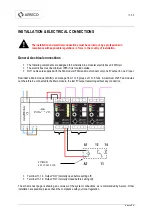
The following components are designed to be installed in a modular electric box unit DIN rail.
The electric box must be minimum IP65 if it is located outside.
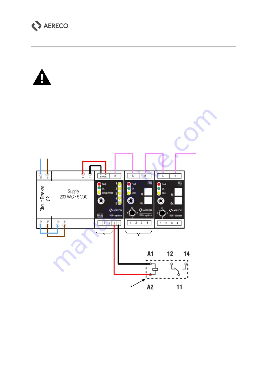
RJ11 cables are supplied with the Fan module (FAN) and must connect only one 'R' output to one 'L' input.
Reminder: a Main module (MAIN) can manage from 1 to 5 groups of 1 to 5 fans. A maximum of 25 Fan modules
can therefore be connected to the Main module, the last 'R' output remaining without any connection
Terminal 11-14 : Output “NO” (normally open before setting off)
Terminal 11-12 : Output “NC” (normally closed before setting off)
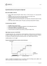
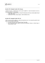
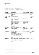
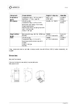
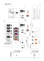
The scheme next page is showing an overview of the system connections, as recommended by Aereco. Other
installation are possible; please check the compliance with your local regulation.
FINDER
40.519.005.0300
Summary of Contents for VBP+
Page 11: ...11 36 Aereco S A ...
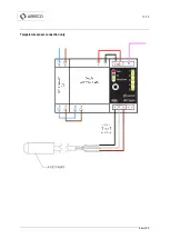
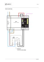
Page 13: ...13 36 Aereco S A Temperature sensor connection only ...
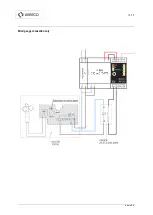
Page 14: ...14 36 Aereco S A Wind gauge connection only ...
Page 15: ...15 36 Aereco S A Clock connection only ...
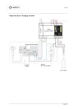
Page 16: ...16 36 Aereco S A Temperature sensor wind gauge connection ...
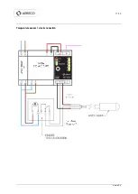
Page 17: ...17 36 Aereco S A Temperature sensor clock connection ...
Page 35: ...35 36 Aereco S A ...


