background image


2/22 


TF5774_C 

Aereco S.A. 


CONTENTS 


CONTENTS ................................................................................................................................................................................ 2


INTRODUCTION ............................................................................................................................................................... 3


W

ARNINGS

 ................................................................................................................................................................. 3


G

ENERAL

 .................................................................................................................................................................... 4


M

AIN FUNCTIONS

......................................................................................................................................................... 4


R

ANGE OF USE

 ............................................................................................................................................................ 4


PRODUCT DATA .............................................................................................................................................................. 5


C

OMPONENTS

 ............................................................................................................................................................. 5


D

IMENSIONS

 ............................................................................................................................................................... 5


T

ECHNICAL DATA

 ......................................................................................................................................................... 6


INSTALLATION ................................................................................................................................................................ 7


F

ITTING ON STACK

 ....................................................................................................................................................... 7


C

ASE OF AN INDIVIDUAL DUCT

 ...................................................................................................................................... 8


C

ASE OF DUCTS GROUPED UNDER A SINGLE FAN

 ........................................................................................................... 8


C

ASE OF DUCTS GROUPED UNDER 

2

 FANS

 .................................................................................................................... 9


A

NTICIPATION OF MAINTENANCE AND CHIMNEY SWEEPING CONSTRAINTS

 ...................................................................... 10


I

NSTALLING THE FAN

 .................................................................................................................................................. 10


CONNECTIONS .............................................................................................................................................................. 11


G

ENERAL CONNECTION DIAGRAM

 ............................................................................................................................... 11


P

OWER CONNECTION

 ................................................................................................................................................ 15


C

ONFIGURING IN 

ST

 OR 

MS

 MODE

 ............................................................................................................................. 16


C

ONNECTION IN 

ST

 MODE

.......................................................................................................................................... 17


C

ONNECTION IN 

MS

 MODE

 ......................................................................................................................................... 17


STARTING UP / OPERATION ........................................................................................................................................ 18


ST

 MODE

 .................................................................................................................................................................. 18


MS

 MODE

 ................................................................................................................................................................. 19


5.3


I

NSTALLATION CHECK UP

 ............................................................................................................................................ 19


MAINTENANCE .............................................................................................................................................................. 20


P

RIOR WARNINGS

 ...................................................................................................................................................... 20


M

AINTENANCE AND CLEANING

 .................................................................................................................................... 20


TECHNICAL ASSISTANCE ............................................................................................................................................ 21


WARRANTY .................................................................................................................................................................... 22


PROTECTION OF THE ENVIRONMENT ....................................................................................................................... 22


Summary of Contents for VB21183

Page 1: ...EN Document not contractual Aereco can realise technical modifications on its products without prior notice Installation and maintenance VBP R Hybrid assistance ventilation fan TF5774_C ENGLISH ...

Page 2: ...8 CASE OF DUCTS GROUPED UNDER 2 FANS 9 ANTICIPATION OF MAINTENANCE AND CHIMNEY SWEEPING CONSTRAINTS 10 INSTALLING THE FAN 10 CONNECTIONS 11 GENERAL CONNECTION DIAGRAM 11 POWER CONNECTION 15 CONFIGURING IN ST OR MS MODE 16 CONNECTION IN ST MODE 17 CONNECTION IN MS MODE 17 STARTING UP OPERATION 18 ST MODE 18 MS MODE 19 5 3 INSTALLATION CHECK UP 19 MAINTENANCE 20 PRIOR WARNINGS 20 MAINTENANCE AND CLE...

Page 3: ...signed to be installed or used by persons whose intellectual and or mental faculties are impaired or who lack experience and knowledge including children unless they have been trained and are supervised by a person responsible for their safety during installation To eliminate any risk of an accident keep them away from the appliance The electrical installation and connection work must be done by a...

Page 4: ... It is therefore possible to change from one version to the other The possible change of configuration will imply a specific identification of the product the label states the baseline configuration MAIN FUNCTIONS Hybrid operation in passive stack or mechanical mode low pressure losses when stopped Compatibility with demand controlled ventilation Low power consumption Direct power supply at 230 V ...

Page 5: ... PRODUCT DATA COMPONENTS Note the MS mode also requires two specific modules a temperature probe and other electrical components These elements are described in the manual specific to this mode DIMENSIONS Dimensions in mm Fan ...

Page 6: ...ctrical design W 42 Inrush protection IP of motor IP54 Control setting of speed By built in potentiometer By MS management system Degree of pollution 1 Characteristics Weight kg 17 Colour Metallic grey black Material envelop Galvanized steel PE Outside dimensions mm 904 x ø610 Installation Number of suction connections available 1 Inlet connection mm ø354 Installation On roof head of duct 3 x ø8mm...

Page 7: ...op of the stack is sufficient For the grouping of ducts an adaptation plenum compliant with the recommendations stated below is necessary to ensure proper aeraulic operation of the whole minimized pressure losses and for attachment and tightness with the fan s General recommendations for the placement of adaptation components The adaptation components must be made of a material strong enough to be...

Page 8: ...st 600 x 600 mm The opening cross section of the duct must not exceed Ø350 mm if it is desired to avoid reducing its cross section The fan must be centred on the duct CASE OF DUCTS GROUPED UNDER A SINGLE FAN For all grouped ducts configurations an adaptation plenum is necessary The plenum must provide a top platform measuring at least 600 x 600 mm provide a circular outlet Ø350 mm centred on the s...

Page 9: ...ed on the outlets Ø350 mm Each Ø350 mm outlet must be at least 1 000 mm from the other and at least 500 mm from the bulkhead separating the volumes The plenum must provide 2 virtual platforms measuring at least 800 x 600 mm each see example below Example of grouping of 8 individual ducts LIMITS All the following cases must be avoided because they would lead to non compliance with European EMC requ...

Page 10: ...s and catches Attachment that can be removed from and refitted on the top plate INSTALLING THE FAN 1 Ensure the proper adaptation of the fan on its stack see section above The plate holding the outlet Ø350 mm can be designed with 3 crimped M8 nuts positioned as shown below to allow the attachment of the fan 2 Remove the fan from the pallet Use only the 2 handles located under the uprights to handl...

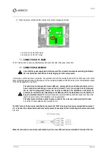
Page 11: ...CONNECTIONS All electrical connection operations must be made by a qualified professional and comply with the standards in force No cable used for the connection may pass though the interior of the stack or of the plenum GENERAL CONNECTION DIAGRAM The following drawings show the electrical connections according to the chosen working mode ST or MS mode Two cases can be identified Case A 230 V elect...

Page 12: ... comply with the installation standards in force colour code in particular have conductors with a cross section of at least 1 5 mm and be able to withstand the environment in which it is installed in particular be resistant to UV Switch general isolating switch A manual circuit breaker must be located on the 230V supply upward the fan s It has to be visible and accessible from each connected fan I...

Page 13: ...13 22 TF5774_C Aereco S A MS mode Case A 230 V electrical box is far from the fans for example in the stairs Case B 230 V electrical box is close to the fans in terrace ...

Page 14: ...14 22 TF5774_C Aereco S A MS mode recommendations ...

Page 15: ... annotation 230 V 50 Hz at its edge Each wire is marked N neutral PE earth protection L phase Edge of the power connection cable Make the connection in accordance with standard practice via an IP65 junction box installed at the base of the fan Recommendation Add a grounding strap and connect it with the M6 screw on the crimped nut provided for this purpose located on the fan casing2 2 Reliée à la ...

Page 16: ...pre configured mode is marked on the label on the outside of the product If you wish to change the management mode proceed as follows Check that the power supply has in fact been cut off for at least 5 minutes before starting to eliminate the risk of electrical shocks from the discharging of certain components 1 Remove the cover from the top of the fan 2 Remove the cover from the protection box of...

Page 17: ...y with the installation standards in force have 4 conductors each having a cross section of at least 1 5 mm be no longer than 25 m between the fan and its management module and be able to withstand the installation environment in particular be resistant to UV Depending on the EMC specific to the installation site the cable must be put in a metallic shield These recommendations ensure the EMC and l...

Page 18: ...e fails to start and begins vibrating slightly Do not touch anything the appliance will itself initiate a starting cycle until it actually starts 2 To adjust the speed unscrew the plug on the left Take all the usual precautions because the appliance is still working Do not insert anything through the unit Set the speed level operating the potentiometer Any curve between the minimum a and maximum b...

Page 19: ...ing key points Actions Comments Check that a 300mA is used for the main differential circuit breaker Measure the power supply 230V in the derivation box for each fan Check that all RJ12 cables between modules are pluged according to the installation and maintenance manual Check the fixation from devices to plenum 3 Ø8mm screws washers Check the grounding strap connection on the fan body insert Che...

Page 20: ...ontrol circuit of the MS version with a risk of injury Never insert anything through the fan and in particular the suction stream in which the turbine is located Never handle an appliance or remove it from its stack when it is connected Cut off the power supply and make sure that it cannot be reconnected Wait for the turbine to come to a full stop MAINTENANCE AND CLEANING We recommend carrying out...

Page 21: ...t that connectors are correctly connected to the engine PCB Make sure there is power supply 230V in each fan bypass box Check into the product s body that there is no foreign body that can make noise or prevent the turbine from rotation Check the coupling s condition visual control Possible cause The main circuit breaker dedicated to the power supply is not a 300 mA Only for R version Connectors a...

Page 22: ...y unqualified personnel If there is any problem please get in touch with your installer or else your dealer PROTECTION OF THE ENVIRONMENT Treatment of the electrical or electronic appliance at end of life applicable in the countries of the European Union and other countries having selective collection systems This logo indicates that the product must not be treated as household waste It must be ta...

Reviews: