background image

29

6 COMMISSIONING

6.1 Setting Fan speed

The speed of the unit can be adjusted during installation according to required ventilation rate. 

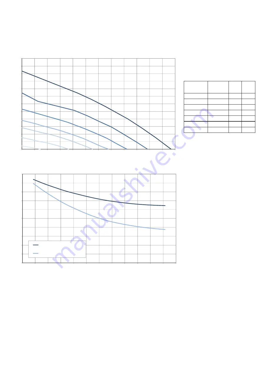
Figure 6. a

 below shows performance curve at different settings of the 0-10V signal to the motors. Consumption refers to the 

2 motors.

Figure 6. b 

indicates the data of the enthalpic heat exchanger.

Table 6. c 

indicates the sound level at the different speeds.

0

50

100

150

200

250

300

350

400

450

500

550

600

0

20

40

60

80

100

120

140

160

180

200

220

240

A

B

C

D

E

F

G

0

10

20

30

40

50

60

70

80

90

100

0

20

40

60

80

100

120

140

160

180

200

220

240

Curva di efficienza termica

Curva di efficienza igrometrica

Fig. 6.a

 Intake curve according to Reg. 

1253/2014 (ErP). 

Curve

Speed %

max

m

3

/h 

max

A (min)

20

10

29

B

40

16

73

C

53

26

110

D

60

36

136

E

72

51

165

F

84

76

197

G (max)

100

114

234

Static Pressure - Pa

Airflow - m

3

/h

Fig. 6.b 

Data of the enthalpic heat exchanger. 

Test conditions:

Indoor air 25°C 50% RH;

External air 5°C 70% RH.

Efficiency

 -

 %

Airflow - m

3

/h

Thermical efficiency curve

Hygrometric efficiency curve

Summary of Contents for DWE4120

Page 1: ...a it www aerauliqa com info aerauliqa it Aerauliqa S r l si riserva il diritto di modificare apportare migliorie ai prodotti e o alle istruzioni di questo manuale in qualsiasi momento e senza preavviso Aerauliqa S r l reserves the right to modify make improvements to products and or this instruction manual at any time and without prior notice MANUALE DI INSTALLAZIONE USO E MANUTENZIONE 2 INSTALLAT...

Page 2: ...sioni delle tubazioni 4 3 4 Spazio richiesto 4 3 5 Etichetta dati 4 4 Trasporto e Stoccaggio 5 5 Installazione 5 5 1 Rimozione dell imballo 5 5 2 Dove come installarlo 5 5 3 Installazione a soffitto 5 5 4 Collegamento elettrico precablato 6 5 5 Collegamenti elettrici aggiuntivi 7 6 Messa in servizio 8 6 1 Settaggio velocità dei ventilatori 8 6 2 Prima di avviare il sistema 9 7 Funzionamento 10 7 1...

Page 3: ...o L apparecchio non deve essere utilizzato in applicazioni diverse da quelle indicate in questo manuale Questo apparecchio può essere utilizzato da bambini di età non inferiore ad 8 anni e da persone con ridotte capacità fisiche sensoriali o mentali o con esperienza e conoscenze insufficienti purché attentamente sorvegliate o istruite su come utilizzare in modo sicuro l apparecchio e sui pericoli ...

Page 4: ...ne dei pannelli di ispezione laterali e frontali 3 2 Dimensioni e Peso A Ingresso aria dall esterno B Espulsione aria verso l esterno C Aria fornita all interno D Aria estratta dall interno Fig 3 c Etichetta dati EXTRACT SUPPLY INTAKE EXHAUST vista lato filtri A B D C 1036 5 9 10 Peso Kg 25 SCATOLA COLLEGAMENTI ELETTRICI 602 536 66 25 Ø125 1036 5 904 738 240 408 128 158 374 374 645 223 66 25 17 66...

Page 5: ...e riscaldate L unità deve essere installata orizzontalmente Montare l unità su superfici piane soffitto E importante che l unità sia completamente posta a livello prima di essere attivata E preferibile posizionare l unità in una stanza separata ad es magazzino lavanderia o similare Scegliendo la zona prestare attenzione che l unità richiede di una manutenzione periodica e che il pannello di ispezi...

Page 6: ...mento elettrico precablato L unità necessita della messa a terra I collegamenti interni sono eseguiti durante l assemblaggio in fabbrica Per il collegamento tra il CTRL DSP e la scheda madre utilizzare un cavo twisted pair 4 poli di lunghezza massima 30m L unità viene fornita pre cablata con cavo di alimentazione 3 fili marrone blu giallo verde cavo di collegamento a CTRL DSP 4 fili verde marrone ...

Page 7: ...ite N 1 uscita on off per elemento riscaldanete pre o post contatto a relais 250Vac 5A Fig 5 g Collegamenti elettrici sulla scheda madre fissata all interno della scatola portacontatti ATTENZIONE Assicurarsi che l interruttore generale dell impianto sia spento prima di qualsiasi operazione di installazione manutenzione ordinaria o straordinaria o collegamento elettrico ATTENZIONE L installazione e...

Page 8: ...locità 0 50 100 150 200 250 300 350 400 450 500 550 600 0 20 40 60 80 100 120 140 160 180 200 220 240 A B C D E F G 0 10 20 30 40 50 60 70 80 90 100 0 20 40 60 80 100 120 140 160 180 200 220 240 Curva di efficienza termica Curva di efficienza igrometrica Fig 6 a Curva di immissione in accordo al Reg 1253 2014 ErP Prodotto testato senza filtro F7 Posizione Velocità W max m3 h max A min 20 10 29 B 4...

Page 9: ...o l esterno Exhaust 59 64 68 62 57 57 54 47 71 44 Involucro Breakout 56 61 64 59 58 50 40 35 68 41 Velocità 80 Lw dB LIVELLO DI POTENZA SONORA PER BANDA DI OTTAVA Lp dB A 63 125 250 500 1 K 2 K 4 K 8K Tot 3m Lato immissione aria dall esterno Intake 55 59 65 60 53 50 44 40 67 41 Lato immissione aria verso l interno Supply 55 59 62 57 51 44 35 28 65 37 Lato estrazione aria dall interno Extract 55 58...

Page 10: ...Fig 7 b CTRL DSP indica ALLARME ERRORE vedere 7 3 per identificare il guasto indica che il Bypass è attivo indica che l ANTI FROST è attivato indica che l ingresso IAQ è attivato es sensore HY CO2 indica che la modalità NIGHT MODE è attivata indica che l uscita Batteria Riscaldante è attivata indica che la modalità Boost è attivata indica che il Timer settimanale è attivato indica che il Timer set...

Page 11: ...oppure Premere OK per selezionare Premere ESC o attendere circa 60 per tornare al menu precedente Modalità Normale 3V DEFAULT Dopo l accensione l unità funziona alla velocità impostata durante l installazione Sul display appare il numero della velocità di funzionamento 1 2 3 Impostazione di fabbrica DEFAULT velocità 1 E possibile variare manualmente la velocità 1 2 3 agendo su oppure In caso sia a...

Page 12: ...e l intervento automatico della velocità aumentata tramite i sensori IAQ remoti l unità funziona alla velocità 1 Al superamento di orario di fine l unità ritorna a funzionare alla velocità precedentemente impostata Premere OK per selezionare Selezionare le voci dei sottomenu usando oppure 1 Abilitazione selezionare ON oppure OFF Impostazione di fabbrica DEFAULT OFF 2 Orario di inizio impostare l o...

Page 13: ...utente 5 Night Mode In caso di utilizzo contemporaneo del Timer settimanale e della funzione Boost vedere funzionamento nel Menu utente 2 Boost Permette di selezionare il Menu installatore Premere OK per entrare nel Menu installatore Premere ESC per tornare al menu precedente Ingresso menu installatore Menu utente 1 Selezione Modalità 2 Boost 3 Durata Boost 4 Reset Allarme FILTRO 5 Night Mode 6 Ti...

Page 14: ...ingresso analogico 0 10V tutte le altre logiche di funzionamento vengono ignorate Se la modalità Slave è attiva l icona e la scritta Slave appaiono sul display Modalità Pressione Costante La funzione al momento non è disponibile Menu installatore 1 Selezione lingua 2 Data ora 4 Modalità Normale 6 Impostazioni Bypass Permette di configurare i parametri di funzionamento della funzione Bypass Premere...

Page 15: ...iscaldamento POST permette di impostare la soglia di intervento dell elemento riscaldante I parametri di settaggio sono 15 C 25 C Aumentare diminuire la temperatura usando oppure Premere OK per selezionare Impostazione di fabbrica DEFAULT 20 C Al superamento della soglia impostata l icona appare sul display Menu installatore 8 Riscaldamento 10 Impostazione Velocità 11 Bilanciamento Portate 12 Filt...

Page 16: ... Aumentare diminuire la velocità usando oppure Premere OK per selezionare Premere ESC per tornare al menu precedente Menu installatore 8 Riscaldamento 10 Impostazione Velocità 11 Bilanciamento Portate 12 Filtro F7 13 Intervallo Allarme Filtro Permette di selezionare il filtro F7 nel caso in cui l unità non lo preveda come standard L eventuale filtro F7 deve essere installato sul lato Aria fornita ...

Page 17: ... OFF e in Timer settimanale OFF Premere OK per entrare Premere ESC per tornare al menu precedente Menu installatore 15 Pressione Costante 17 Scarico periodico 18 Ore di funzionamento unità 19 Impostazioni Modbus 20 Salva Impostazioni L unità è predisposta per comunicare via Modbus RTU su RS485 Per le specifiche contattare il nostro servizio clienti Menu installatore 15 Pressione Costante 17 Scaric...

Page 18: ...L DSP Descrizione codice errore Fig 7 b E000 manca collegamento RS485 fra il CTRL DSP e la scheda madre E001 il ventilatore di espulsione non funziona Fig 8 a E002 il ventilatore di immissione non funziona Fig 8 a E003 termistore T11 rotto scollegato Fig 7 a E004 termistore T12 rotto scollegato Fig 7 a E005 termistore T21 rotto scollegato Fig 7 a E006 termistore T22 rotto scollegato Fig 7 a E007 a...

Page 19: ...giungere ulteriore calore Il pacco scambiatore è rimovibile per la pulizia e la manutenzione durante l operazione di manutenzione straordinaria Termistori Le sonde di temperatura attivano o meno le funzioni che dipendono dalla combinazione delle temperature esterne e interne 8 1 Lista componenti 1 2 3 4 5 6 7 8 9 FILTRO G4 ARIA ESTRATTA DALL INTERNO FILTRO G4 ARIA IMMESSA DALL ESTERNO SCAMBIATORE ...

Page 20: ...zione e la manutenzione dell unità e del sistema di ventilazione completo deve essere eseguito da un installatore autorizzato e in conformità alle leggi e ai regolamenti vigenti 8 3 Manutenzione ordinaria Tenere la superficie dell unità pulita dalla polvere Pulire i filtri con un aspirapolvere seguendo le seguenti illustrazioni fig 8 b c d e quando il segnale FILTER appare sul display LCD Ciò può ...

Page 21: ...terne e della frequenza con la quale vengono puliti i filtri Per estrarre il pacco scambiatore sbloccare l apposita staffa di fissaggio tramite la vite gialla Fig 8 f j k l m n Fig 8 o Pulire i ventilatori ogni anno con un aspirapolvere La necessità di eseguire questa operazione può variare da caso in caso a seconda delle condizioni ambientali interne ed esterne Non rimuovere mai le graffette di b...

Page 22: ...pannello di comando CTRL DSP fornito di serie 2 Verificare griglie e diffusori E necessario resettare o pulire le griglie diffusori Odori spiacevoli 1 Verificare i filtri E necessario cambiarli 2 Verificare il sistema di tubazioni le griglie e i diffusori E necessario pulirli Informativa sullo smaltimento delle unità a fine vita Questo prodotto è conforme alle Direttiva EU 2002 96 EC Il simbolo de...

Page 23: ...nsions and Weight 25 3 3 Duct connections 25 3 4 Space required 25 3 5 Rating label 25 4 Transport and Storage 26 5 Installation 26 5 1 Unpacking 26 5 2 Where how to install 26 5 3 Ceiling installation 26 5 4 Precabled electric connections 27 5 5 Additional electric connections 28 6 Commissioning 29 6 1 Setting Fan speed 29 6 2 Before Starting the System 30 7 Operation 31 7 1 User Menu on CTRL DSP...

Page 24: ... used for applications other than those specified in this manual This appliance can be used by children aged from 8 years and above and persons with reduced physical sensory or mental capabilities or lack of experience and knowledge if they have been given supervision or instruction concerning use of the appliance in a safe way and understand the hazards involved Children shall not play with the a...

Page 25: ...utside C Supply air to inside D Extract air from inside EXTRACT SUPPLY INTAKE EXHAUST filter side view A B D C 602 536 66 25 Ø125 1036 5 904 738 240 408 128 158 374 374 645 223 66 25 17 66 25 353 232 319 269 259 243 1036 5 9 10 Weight Kg 25 TERMINAL BOX 602 536 66 25 Ø125 1036 5 904 738 240 408 128 158 374 374 645 223 66 25 17 66 25 353 232 319 269 259 243 filter side view 904 738 66 25 240 536 60...

Page 26: ...a heated space The unit must always be mounted horizontally Mount the unit on flat surface ceiling It s important that the unit is completely leveled before it is put into operation Place the unit preferably in a separate room e g storage laundry room or similar When choosing the location it should be kept in mind that the unit requires maintenance regularly and that the inspection door should be ...

Page 27: ...tly 5 4 Precabled electric connections The unit must be earthed The QR230E is wired internally from factory To connect the the CTRL DSP to the mother board use a 4 poles twisted pair cable 30m max length Unit comes pre wired with mains supply cable 3 core brown blue yellow green control cable for connection to CTRL DSP 4 core green brown yellow white cable for connection to remote sensor 2 core bl...

Page 28: ...ly Outputs N 1 on off output for pre heating post heating relay contact 250Vac 5A Fig 5 g Electrical connections on the motherboard fitted in the terminal box WARNING Make sure that the mains supply to the unit is disconnected before performing any installation service maintenance or electrical work WARNING The installation and service of the unit and complete ventilation system must be performed ...

Page 29: ...300 350 400 450 500 550 600 0 20 40 60 80 100 120 140 160 180 200 220 240 A B C D E F G 0 10 20 30 40 50 60 70 80 90 100 0 20 40 60 80 100 120 140 160 180 200 220 240 Curva di efficienza termica Curva di efficienza igrometrica Fig 6 a Intake curve according to Reg 1253 2014 ErP Curve Speed W max m3 h max A min 20 10 29 B 40 16 73 C 53 26 110 D 60 36 136 E 72 51 165 F 84 76 197 G max 100 114 234 St...

Page 30: ...62 69 64 58 56 49 46 71 45 Supply 56 62 65 61 55 50 40 31 68 41 Extract 57 61 65 60 55 49 41 32 68 41 Exhaust 59 64 68 62 57 57 54 47 71 44 Breakout 56 61 64 59 58 50 40 35 68 41 Speed 80 Lw dB SOUND POWER OCTAVE BAND Lp dB A 63 125 250 500 1 K 2 K 4 K 8K Tot 3m Intake 55 59 65 60 53 50 44 40 67 41 Supply 55 59 62 57 51 44 35 28 65 37 Extract 55 58 62 55 51 43 35 28 65 37 Exhaust 58 61 65 58 53 52...

Page 31: ...ERROR ALARM see 7 3 to check the type of error shows that the Bypass is active shows that ANTI FROST is active shows that the IAQ input is activated i e HY CO2 shows that NIGHT MODE is activated shows that Heating output is activated shows that the Boost is active shows that the weekly timer is activated shows that the weekly timer is deactivated shows that the SLAVE functionality is activated 7 O...

Page 32: ...ress OK to select Press ESC or wait for about 60 seconds to go back to the previous menu Normal Mode 3V DEFAULT Once powered on the unit runs at the speed selected during the installation The speed number 1 2 3 is displayed on the LCD Factory setting DEFAULT speed 1 The speed 1 2 3 can be manually changed using or In case the IAQ sensor input is activated as per Fig 5q e g HY or IAQ sensor the uni...

Page 33: ...lows to deactivate the automatic operation of the speed increased via remote IAQ sensors the unit operates at speed 1 When the ending time is elapsed the unit returns to operate at the selected speed Press OK to select Select the submenu item using or 1 Enabling select ON or OFF Factory setting DEFAULT OFF 2 Starting Time set the time Factory setting DEFAULT 20 00 o clock 8 p m 3 Ending Timer set ...

Page 34: ...imer and the Boost functionality need to be used make reference to the User Menu 2 Boost for more details It allows to select the Installer menu Press OK to enter the Installer menu Press ESC to go back to the previous menu Enter installer menu User Menu 1 Mode Selection 2 Boost 3 Boost Duration 4 Reset FILTER Alarm 5 Night Mode 6 Weekly timer 7 Installer Menu User Menu 1 Mode Selection 2 Boost 3 ...

Page 35: ...speed by means of the 0 10V analogic input any other operation logic is ignored If the Slave mode is activated the icon and the word Slave are displayed Constant Pressure Mode Currently not available Installer Menu 1 Language 2 Date time 4 Normal Mode 6 Bypass settings It allows to set the Bypass operation parameters Press OK to enter Select the submenu item using or and press OK to confirm 1 Desi...

Page 36: ...AT output Fig 5g is activated 3 Heating threshold POST it allows to set the heating threshold The setting range is 15 C 25 C Increase decrease the temperature using or Press OK to select Factory setting DEFAULT 20 C If the heater is activated the icon is displayed Installer Menu 8 Heating 10 Speed setting 11 Airflow Balancing 12 F7 filter 13 Filter Alarm interval It allows to adjust the speeds in ...

Page 37: ...for any speed DEFAULT 0 Increase decrease the speed using or Press OK to select Press ESC to go back to the previous menu Installer Menu 8 Heating 10 Speed setting 11 Airflow Balancing 12 F7 filter 13 Filter Alarm interval It allows to select the F7 filter in case the unit is not equipped with it from factory The F7 filter should be installed to the supply air side T22 Fig 7a Press OK to enter Cho...

Page 38: ...er is OFF Press OK to enter Press ESC to go back to the previous menu Installer Menu 15 Constant Pressure 17 Periodic purge 18 Working Hours Counter 19 ModBus settings 20 Save settings The unit can be controlled via ModBus ModBus RTU over RS485 For specification contact our customer service Installer Menu 15 Constant Pressure 17 Periodic purge 18 Working Hours Counter 19 ModBus settings 20 Save se...

Page 39: ...or description Fig 7b E000 no RS485 connection between the CTRL DSP and the motherboard E001 no rotation of the exhaust air fan Fig 8 a E002 no rotation of the intake air fan Fig 8 a E003 thermistor T11 broken disconnected Fig 7 a E004 thermistor T12 broken disconnected Fig 7 a E005 thermistor T21 broken disconnected Fig 7 a E006 thermistor T22 broken disconnected Fig 7 a E007 alarm BST input E008...

Page 40: ...tenance free It is possible to easily disconnect and replace the fans if necessary Filters The 2 filters are of filter quality G4 for both the supply air and extract air filter The filters need to be cleaned regularly and replaced when polluted during maintenance New sets of filters can be acquired from your installer or wholesaler Heat exchanger The unit is equipped with a highly efficient counte...

Page 41: ...8 d Fig 8 c Fig 8 b H Keep the unit surface free from dust Clean the filters with a vacuum cleaner following the following illustrations Fig 8f g h i when the FILTER signal is displayed on LCD Their maintenance may differ per situation depending on the internal and external environmental conditions Press FILTER button Fig 7 b to reset the Filter Alarm Filters must be replaced every year 8 4 Servic...

Page 42: ...remove the heat exchanger unlock the specific bracket by turning the yellow screw Fig 8 f j k l m n Fig 8 i Fig 8 h Clean the fans every year with a vacuum cleaner This may differ per situation depending on internal and external environmental conditions and on frequency of filter cleaning Do not move the balance clips of the fan Fig 8 f j k o Fig 8 j Fig 8 k Fig 8 l Fig 8 m Fig 8 n Fig 8 o ...

Page 43: ...nd diffusers Re setting or cleaning of grilles and diffusers required Unpleasant smell 1 Check filters Change of filters required 2 Check ducting system and grilles and diffusers Cleaning required Information on disposal of units at the end of life This product complies with EU Directive 2002 96 EC The symbol of the crossed out dustbin indicates that this product must be collected separately from ...

Page 44: ...entrale Central demand control Controllo manuale no DCV Manual control no DCV o1 Trafilamento interno massimo Maximum internal leakage rate 2 5 o2 Trafilamento esterno massimo Maximum external leakage rate 1 p1 Tasso di miscela interno Internal mixing rate N A p2 Tasso di miscela esterno External mixing rate N A q Segnale avvertimento filtro Visual filter warning Avviso su display FILTER Visual fi...

Page 45: ...45 NOTE ...

Page 46: ...46 NOTE ...

Page 47: ...47 NOTE ...

Page 48: ...EA BS 528635 Tel 39 030 674681 Fax 39 030 6872149 www aerauliqa com info aerauliqa it Aerauliqa srl si riserva il diritto di modificare apportare migliorie ai prodotti e o alle istruzioni di questo manuale in qualsiasi momento e senza preavviso Aerauliqa srl reserves the right to modify make improvements to products and or this instruction manual at any time and without prior notice ...

Reviews: