background image

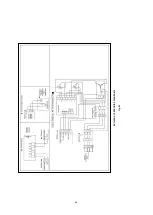
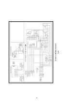
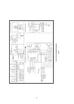
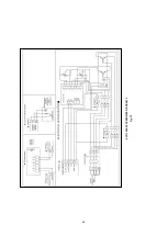
60 


EVO

-95

R

 A

C

C

E

S

S

O

R

IE

S

 D

IA

G

R

A

M

 2


Fig. 

64


Summary of Contents for EVO-R

Page 1: ...User s Manual EVO R COMPACT AIR HANDLING UNIT WITH ROTARY HEAT RECOVERY ...

Page 2: ...nce curve Page 18 CHAPTER 5 SERVICE AND MAINTENANCE 5 0 Service and maintenance Page 20 5 1 Service and maintenance of rotary heat exchanger Page 20 5 2 Filter change Page 23 5 3 Service and maintenance of fan Page 24 5 4 Module assembly Page 26 5 5 Terminal box with isolator main switch Page 26 CHAPTER 6 Installation service and maintenance of accessories 6 1 Accessory list Page 27 6 2 Installati...

Page 3: ...Diagrams 7 4 EVO 50R Wiring Diagrams 7 5 EVO 60R Wiring Diagrams 7 6 EVO 80R Wiring Diagrams 7 7 EVO 95R Wiring Diagrams 7 8 EVO 120R Wiring Diagrams 7 9 EVO 150R Wiring Diagrams CHAPTER 8 SPARE PART LIST 8 1 Spare part list Page 41 Page 33 Page 37 Page 41 Page 45 Page 49 Page 53 Page 57 Page 61 Page 65 Page 69 ...

Page 4: ...y and safely in the event that they are installed in accordance with the instructions in the operating instructions and the operating and maintenance requirements are fully All maintenance procedures required for the device must be carried out by experts and authorized persons Warranty Conditions The devices are warranted against defects in material and workmanship for two 2 years During the warra...

Page 5: ...er immediately In case of delayed notification any possible claim may be void 1 5 Storage When storing for a prolonged time the following steps are to be taken to avoid damaging influences Protection by dry air dustproof packing plastic bags with drying agent and moisture indicators The storage place must be water protected vibration free and free of temperature variations Ambient temperature limi...

Page 6: ...Various sensors e g CO2 or humidity sensors accessory are available on request with which automatic fan control is possible If the device is used at 5 C it is necessary to use a heater in the device electronic box not included scope of delivery optional The standard equipment permits the installation and the application in frost free rooms 5 C If the unit is to be used in outdoor it is necessary t...

Page 7: ...x7 3x8 4 11x11x12 1 10 7x10 7x12 3 15 2x15 2x16 9 18 3x18 3x19 9 Power consumption ventilation kW 0 5 0 78 1 5 2 5 2 4 3 6 3 5 5 6 Max power consumption kW 5 4 7 6 12 3 5 2 5 7 4 7 4 10 4 12 4 Voltage Frequency 3 400V 50Hz 3 400V 50Hz 3 400V 50Hz 3 400V 50Hz 3 400V 50Hz 3 400V 50Hz 3 400V 50Hz 3 400V 50Hz 3 400V 50Hz Filter class extract outdoor air ePM10 50 M5 ePM1 55 F7 ePM10 50 M5 ePM1 55 F7 eP...

Page 8: ... 4 52 8 63 6 63 6 62 4 64 1 67 2 63 5 Effective electric power input kW 0 48 0 77 1 12 2 46 2 34 3 27 3 25 4 88 5 57 Face velocity m s 1 4 2 03 1 76 1 71 1 75 1 85 1 89 2 07 1 94 Normal external pressure Pa 250 250 300 350 350 350 350 350 350 Internal pressure drop of ventilation components Pa 274 368 310 274 280 288 298 334 302 SFPint W m3 s 926 1183 1157 847 867 908 914 976 936 Declared maximum ...

Page 9: ...ciency of the system Important notes 1 The ventilation ducts must not become kinked 2 Any kind of connections valves flanges etc which associated with fluids like that air or water must be tight and leakproof 3 If necessary vibration isolators can be used between unit and floor 4 In order to prevents sound transmission appropriate acoustic decoupling must be provided on site depending on the build...

Page 10: ...igot optional 2 2 Installation EVO R has easily adjustable stays Fig 2 First of all make sure that there is enough space for the device servicing Therefore the device must be assembled after the dimensions have been identified Make sure that the device is placed on a flat surface before any assembly work 2 3 Flange connection adapter pieces EVO R flange connection diameters are shown below Fig 3 F...

Page 11: ...or hoods to the system is not permitted reasons dirt fire danger hygiene All fire and building regulations must be observed 2 6 Electrical Connection The unit must be fully isolated from the mains power supply before any maintenance and installation work or before opening the enclosure The electrical connection must only be carried out by an authorised qualified electrician in accordance with the ...

Page 12: ...5 8 8 2 7 9 6 3 11 1 Terminal box 2 Exhaust air fan 3 Supply air fan 4 Outdoor air pre filter ePM10 50 optional 5 Extract air filter ePM10 50 6 Outdoor air main filter ePM1 55 7 Rotary heat exchanger 8 Outdoor damper optional 9 Water heater coil or electrical after heater optional 10 Main switch 11 Casing Fig 4 ...

Page 13: ... box 2 Exhaust air fan 3 Supply air fan 4 Outdoor air pre filter ePM10 50 optional 5 Extract air filter ePM10 50 6 Outdoor air main filter ePM1 55 7 Rotary heat exchanger 8 Outdoor damper optional 9 Recirculation damper optional 10 Main switch 11 Casing 8 10 1 6 2 8 7 4 5 9 3 11 Fig 5 ...

Page 14: ...e unit EVO 15R EVO 20R EVO 30R Fig 6 MODEL A B C D E F K L M N X Y Dimensions mm Fig 6 EVO 15R 1295 990 155 1700 760 910 205 360 415 520 350 310 EVO 20R 1400 1090 155 1700 860 1010 205 360 415 520 470 310 EVO 30R 1500 1200 155 1700 970 1120 205 360 415 520 580 410 Fig 6 ...

Page 15: ...15 MODEL AA BB CC DD EE FF GG HH Dimensions mm Fig 7 EVO 15 R 680 568 472 93 5 150 463 2 263 4 380 EVO 20 R 670 568 472 143 5 150 514 2 286 4 430 EVO 30 R 680 568 472 193 5 150 573 2 313 4 485 Fig 7 ...

Page 16: ...610 1230 555 440 690 855 410 EVO 60R 1895 1590 155 2015 1360 1510 680 1330 625 480 748 855 410 EVO 80R 2145 1840 155 2100 1610 1760 750 1350 1055 410 EVO 95R 2245 1940 155 2315 1710 1860 830 1480 775 605 775 1200 410 EVO 120R 2400 2090 155 2450 1860 2010 895 1550 840 605 845 1475 510 EVO 150R 2645 2340 155 2535 2110 2260 940 1590 890 620 870 1600 710 Fig 8 ...

Page 17: ...30 4 106 EVO 60 R 150 125 568 690 472 446 5 680 785 402 5 179 6 130 4 106 EVO 80 R 150 568 472 805 429 6 130 4 106 EVO 95 R 150 125 568 840 472 616 5 855 960 490 5 529 6 130 4 106 EVO 120 R 150 125 568 910 472 696 5 930 1035 527 5 679 6 130 4 106 EVO 150 R 150 125 568 950 472 816 5 1055 1160 589 5 929 6 130 4 106 Fig 9 ...

Page 18: ...18 4 1 Performance curve ...

Page 19: ... Danger of electric shock moving parts fan and hot surfaces Maintenance is restricted to regular visual inspections Inspections should be initially carried out about every 3 months and then after trouble free operation can be extended to 12 months The following must be checked Tension of drive belt Quality of bearings assess by bearing noise Function of slide seal Condition of casing RISK OF INJUR...

Page 20: ...lectrical connections easily 6 3 Service and maintenance of the fan 3 Unplug the electrical connections on the varimax drive unit Fig 11 3 Pull lock bars for unlock heat exchanger Fig 12 4 Pull the heat exchanger to remove Fig 13 Fig 11 Fig 12 Fig 13 ...

Page 21: ...e nozzle adjusted to plane jet 3 Vary the spray angle between 30 and 30 degrees from the openings at a distance of 300 mm 11 81 from the entrance 4 Spray the whole wheel Don t forget to rotate the wheel in order to clean the parts hidden behind the framework 5 Let the heat exchanger air dry 6 Spray the heat exchanger with detergent with a low pressure sprayer 7 Repeat point 1 5 in order to remove ...

Page 22: ... 50 M5 96 EVO 80R Outdoor air filter ELF EVO 80R ePM1 55 F7 96 EVO 95R Extract air filter ELF EVO 95R ePM10 50 M5 96 EVO 95R Outdoor air filter ELF EVO 95R ePM1 55 F7 96 EVO 120R Extract air filter ELF EVO 120R ePM10 50 M5 96 EVO 120R Outdoor air filter ELF EVO 120R ePM1 55 F7 96 EVO 150R Extract air filter ELF EVO 150R ePM10 50 M5 96 EVO 150R Outdoor air filter ELF EVO 150R ePM1 55 F7 96 The filt...

Page 23: ...he fans are heavy 1 Unlock the lock and turn the handles counter clock wise direction for opening doors Fig 16 2 Unplug the power connector on the fan Fig 17 3 Remove the fan pressure hoses from pressure transmitter Fig 18 Fig 19 Fig 16 Fig 17 Fig 18 ...

Page 24: ... connections when installing the fans back into 5 4 Module assembly RISK OF INJURY Make sure that the power connection is disconnected and fan is not moving before doing any work on the device 1 Bring modules closer together and tighten the bolt Fig 21 Fig 19 Fig 20 Fig 21 ...

Page 25: ...25 2 Plug the electrical connections Fig 22 5 5 Terminal box with isolator main switch The terminal box is connected to the top of the casing ensures free access to the electronic component Fig 22 ...

Page 26: ... Flexible Connection Sound Attenuator Weather Roof Weather Roof REc Weather Roof pre heater electrical Weather Roof after heater electrical Weather Roof after heater ww left right Weather Roof cooling CW left Weather Roof cooling CW right Weather Roof cooling DX left Weather Roof cooling DX right Outdoor Air Spigot Outdoor Exhaust Air Spigot Outdoor Vibration Damper Pad E3 DSP Display ED T7 Displa...

Page 27: ...ection is disconnected and fan is not moving before doing any work on the device Danger of electric shock moving parts fan and hot surface 1 Remove the service panel Fig 23 EVO 15R EVO 20R EVO 30R 2 Place the electrical after heater Fig 24 3 Plug the electrical connections on the electrical heater Fig 25 Fig 23 Fig 24 Fig 25 ...

Page 28: ...INJURY Make sure that the power connection is disconnected and fan is not moving before doing any work on the device Danger of electric shock moving parts fan and hot surface 1 Remove the filter lock Fig 26 2 Place the filter lock as shown below Fig 27 Fig 26 Fig 27 ...

Page 29: ...at the power connection is disconnected before doing any work on the device 1 Bring modules closer together Fig 28 2 Fasten the cables with cable tie and plug the electrical connections Fig 29 3 Tighten the bolt Fig 30 Fig 28 Recirculation module Fig 29 Fig 30 ...

Page 30: ...nnection is disconnected before doing any work on the device Before the damper installation remove the filter and fan 1 Loosen the screw Fig 31 2 Placed the damper from the ears to the bolts and tighten the bolts at the top and bottom of the damper Fig 32 Fig 31 Fig 32 ...

Page 31: ...31 3 Plug the electrical connections on the damper actuator Fig 34 Fig 33 Fig 34 ...

Page 32: ... is disconnected before doing any work on the device Make sure there is no hot water connection before doing any work on the device Danger of electric shock moving parts fan and hot surfaces Refer to the electrical diagrams for hot water coil signal connections Hot water coil inlet outlet pipes should be insulated 0 10 20 30 40 50 60 70 80 90 0 2000 4000 6000 8000 10000 12000 14000 16000 Water con...

Page 33: ...33 CHAPTER 7 WIRING DIAGRAM OVERVIEW 7 1 EVO 15R Wiring Diagrams EVO 15R STANDART UNIT WIRING DIAGRAM Fig 37 ...

Page 34: ...34 Fig 38 EVO 15R CONTROL PANEL DIAGRAM ...

Page 35: ...35 EVO 15R ACCESSORIES DIAGRAM 1 Fig 39 ...

Page 36: ...36 EVO 15R ACCESSORIES DIAGRAM 2 Fig 40 ...

Page 37: ...37 7 2 EVO 20R Wiring Diagrams EVO 20R STANDART UNIT WIRING DIAGRAM Fig 41 ...

Page 38: ...38 EVO 20R CONTROL PANEL DIAGRAM Fig 42 ...

Page 39: ...39 EVO 20R ACCESSORIES DIAGRAM 1 Fig 43 ...

Page 40: ...40 EVO 20R ACCESSORIES DIAGRAM 2 Fig 44 ...

Page 41: ...41 7 3 EVO 30R Wiring Diagrams EVO 30R STANDART UNIT WIRING DIAGRAM Fig 45 ...

Page 42: ...42 EVO 30R CONTROL PANEL DIAGRAM Fig 46 ...

Page 43: ...43 EVO 30R ACCESSORIES DIAGRAM 1 Fig 47 ...

Page 44: ...44 EVO 30R ACCESSORIES DIAGRAM 2 Fig 48 ...

Page 45: ...45 7 4 EVO 50R Wiring Diagrams EVO 50R STANDART UNIT WIRING DIAGRAM Fig 49 ...

Page 46: ...46 EVO 50R CONTROL PANEL DIAGRAM Fig 50 ...

Page 47: ...47 EVO 50R ACCESSORIES DIAGRAM 1 Fig 51 ...

Page 48: ...48 EVO 50R ACCESSORIES DIAGRAM 2 Fig 52 ...

Page 49: ...49 7 5 EVO 60R Wiring Diagrams EVO 60R STANDART UNIT WIRING DIAGRAM Fig 53 ...

Page 50: ...50 EVO 60R CONTROL PANEL DIAGRAM Fig 54 ...

Page 51: ...51 EVO 60R ACCESSORIES DIAGRAM 1 Fig 55 ...

Page 52: ...52 EVO 60R ACCESSORIES DIAGRAM 2 Fig 56 ...

Page 53: ...53 7 6 EVO 80R Wiring Diagrams EVO 80R STANDART UNIT WIRING DIAGRAM Fig 57 ...

Page 54: ...54 EVO 80R CONTROL PANEL DIAGRAM Fig 58 ...

Page 55: ...55 EVO 80R ACCESSORIES DIAGRAM 1 Fig 59 ...

Page 56: ...56 EVO 80R ACCESSORIES DIAGRAM 2 Fig 60 ...

Page 57: ...57 7 7 EVO 95R Wiring Diagrams EVO 95R STANDART UNIT WIRING DIAGRAM Fig 61 ...

Page 58: ...58 EVO 95R CONTROL PANEL DIAGRAM Fig 62 ...

Page 59: ...59 EVO 95R ACCESSORIES DIAGRAM 1 Fig 63 ...

Page 60: ...60 EVO 95R ACCESSORIES DIAGRAM 2 Fig 64 ...

Page 61: ...61 7 8 EVO 120R Wiring Diagrams EVO 120R STANDART UNIT WIRING DIAGRAM Fig 65 ...

Page 62: ...62 EVO 120R CONTROL PANEL DIAGRAM Fig 66 ...

Page 63: ...63 EVO 120R ACCESSORIES DIAGRAM 1 Fig 67 ...

Page 64: ...64 EVO 120R ACCESSORIES DIAGRAM 2 Fig 68 ...

Page 65: ...65 7 9 EVO 150R Wiring Diagrams EVO 150R STANDART UNIT WIRING DIAGRAM Fig 69 ...

Page 66: ...66 EVO 150R CONTROL PANEL DIAGRAM Fig 70 ...

Page 67: ...67 EVO 150R ACCESSORIES DIAGRAM 1 Fig 71 ...

Page 68: ...68 EVO 150R ACCESSORIES DIAGRAM 2 Fig 72 ...

Page 69: ...ly Fresh Air Fan Assembly Heat Exchanger Step Motor and Controller Rotor Rotational Sentinel Thermal wheel chain Main PCB Presigo PCB Main Transformer Fuse Fuse holder Main switch Terminal box Cover Terminal box mainpart w top hat rail HMI Connection Cable 5m Relais Bypass motor WW CW pump Air Temperature Sensor PT1000 Door handle Service Panel hinge Service Panel Lock Unit Foot PVC Foam Gasket 5x...

Reviews: