Clamp-On Ground Resistance Tester Model 3705
USER MANUAL
I N S T R U M E N T S
HOLD
+
–
mA
R 1
MEM
MR
NOISE
Model 3705
GROUND TESTER
ON
OFF
150V CAT III
Page 1: ...Clamp On Ground Resistance Tester Model 3705 USER MANUAL I N S T R U M E N T S HOLD mA R 1 HOLD MEM MR NOISE Model 3705 GROUND TESTER ON OFF 150V CAT III ...
Page 2: ...file AEMC Instruments will at its option repair or replace the faulty material If a registration card is not on file we will require a dated proof of purchase as well as your REGISTRATION CARD accompanied by the defective material REGISTER ONLINE AT www aemc com Warranty Repairs What you must do to return an Instrument for Warranty Repair First request a Customer Service Authorization Number CSA b...
Page 3: ...ical Specifications 7 Ground Resistance 7 Mechanical Specifications 7 Safety Specifications 8 Model 3705 Controls 9 Digital Display Features 10 Function Controls 12 On Off 12 Auto Off 13 Hold 13 Resistance 14 Function Access Summary 15 Principle of Operation 15 Field Applications 17 Pole Ground Rods 17 Service Entrance or Meter 18 Pad Mounted Transformer 19 Transmission Towers 20 Central Office Lo...
Page 4: ...ne Space 24 General Measurement Notes 24 Calibration Check Loop 25 Commonly Asked Questions 26 Maintenance 27 Warning 27 Battery Replacement Procedure 28 Troubleshooting 28 Repair and Calibration 29 Technical and Sales Assistance 29 ...
Page 5: ...use the instrument to twist or pry the ground electrode or ground wire away from the equipment being grounded Open and close the clamp on jaws slowly ensuring proper alignment AEMC Instruments considers the use of rubber gloves to be an excellent safety practice even if the equipment is properly operated and correctly grounded International Electrical Symbols This symbol signifies that the instrum...
Page 6: ...accuracy depends on the proper jaw closing For any measurement make sure that the jaw mating surfaces are clean and that no foreign matter obstructs their closing Description The Ground Resistance Tester Model 3705 measures ground rod and small grid resistance through any season without the use of auxiliary ground rods Clamp on ground resistance testers are used in multi grounded systems without d...
Page 7: ...es and in manholes The large opening accommodates not only ground rods but larger ground conductors up to 1000 MCM typically found in telecommunication or railroad applications The inner jaw is composed of two independent and individually shielded magnetic cores permitting the injection of a test signal and accurate return signal measurement without noise interference or cross talk common to separ...
Page 8: ...m conductor centered loop resistance noninductive Accuracy of Reading Frequency 50 60Hz Resistance Measurement Frequency 2403Hz Voltage Generated into the Loop Approx 60mVrms Resistance Overload OL displayed above 1200Ω Mechanical Specifications Dimensions 9 25 x 3 94 x 2 17 235 x 100 x 55mm Weight 2 2lbs 1kg Case Material Lexan 920A UL94V2 or equivalent Jaw Cover Material Lexan with 10 fiberglass...
Page 9: ...28 mm US Design Patent No 362 639 Safety Specifications IEC 1010 2 032 Class 2 Double Insulation Working Voltage 150V Cat III Pollution Degree 2 300V Cat II Pollution Degree 2 Environmental IP30 Protection Index EN 60529 Ed 92 IK04 EN 50102 Ed 95 Vibration Test IEC 68 2 6 Shock Test IEC 68 2 27 Drop Test 1m IEC 68 2 32 Max A Overload 100A continuous 200A 5s 50 60Hz OL displayed above 29 99Arms Ele...
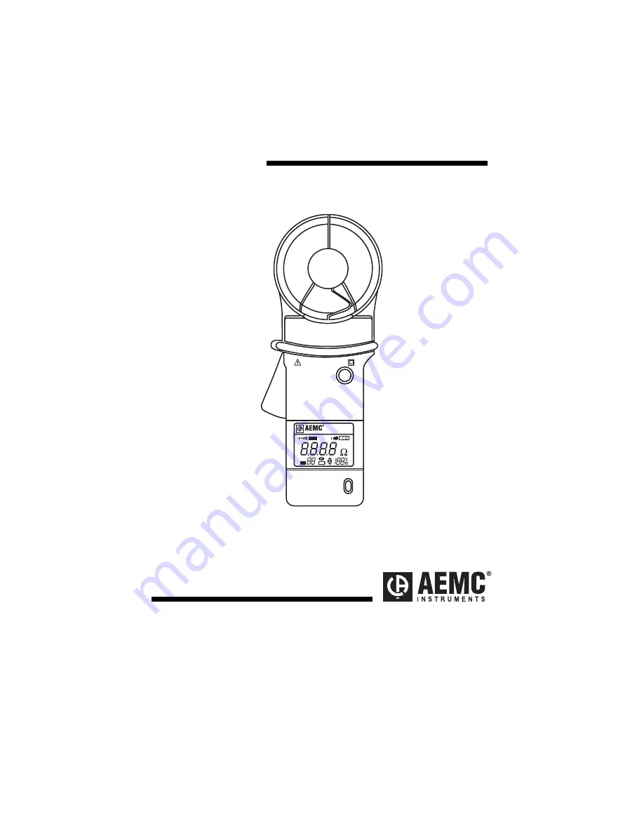
Page 10: ...l 3705 GROUND TESTER ON OFF 150V CAT III 1 2 3 4 5 1 Head Assembly Consists of two individually shielded magnetic cores 2 Hold Freezes last measured value on the display 3 Display 3000 count LCD function indicators 4 ON OFF Power ON or OFF activates display self test at power up 5 Lever Opens or closes jaws Figure 1 ...
Page 11: ...atter in the jaw mating surface In the Ω function this symbol indicates the presence of excessive stray noise in the ground electrode under test This symbol will be present if noise signals reach an amplitude of approx 5A or 50V Resistance measurement values are no longer valid The beeper is also activated Displayed when measured resistance is below 0 1Ω This may indicate that grounding electrode ...
Page 12: ...second during a low battery condition Measurements are still possible When this symbol is displayed continuously measurements are no longer possible Battery replacement is necessary Indicates the approximate percentage of useful battery life remaining 0 100 This function is displayed only upon initial power up when the ON push button is held down for more than 2 seconds The overload symbol will il...
Page 13: ... ON push button is pushed and held down after three seconds the instrument will beep and provide a self test featuring a full function display Fig 3 followed by status indications for the remaining battery life battery symbol blinks 0 100 Fig 4 Release the ON OFF push button to initialize the instrument mA R 1 R 1 HOLD MEM MR NOISE ON OFF mA HOLD NOISE ON OFF Model 3705 GROUND TESTER I N S T R U M...
Page 14: ... the Auto Off feature has been disabled Fig 5 Hold The HOLD push button freezes the last measured value onto the display When the HOLD function is enabled HOLD is displayed on the LCD When the HOLD function is enabled other control functions are disabled To exit HOLD press the HOLD push button and normal operation is resumed Note When HOLD is pressed during power up the auto off feature is disable...
Page 15: ...o 0 07Ω and indicate R 1 below 0 1Ω Fig 7 Accuracy is not defined below 0 1Ω Measurements below 0 1Ω typically or even 1Ω indicate the ground tester is clamped onto a closed loop and that the signal is not flowing through the ground under test If the resistance readings are above 1200Ω OL will be displayed on the LCD Fig 9 This may indicate high ground resistance but may also be caused by a discon...
Page 16: ... constant voltage oscillator The resulting current is then sensed by a detection CT An active filter is used to dampen earth current at commercial frequency and high frequency noise Example If we clamp around any grounding electrode in a multi grounded system the measured value of the electrode under test will be the resistance of that particular rod in series with the equivalent parallel resistan...
Page 17: ...Ground Resistance Tester Models 3705 16 I V Rx R1 R2 Rn 1 Rn Figure 9 Rx R1 Rn Rn 1 Figure 10 ...
Page 18: ... neutral or ground wire to the ground rod or rods as the circuit provides The reading you measure with the clamp on tester indicates not just the resistance of the rod but of the connection to the system neutral and all bonding connections between the neutral and the rod Note that in Fig 11 there is both a butt plate and a ground rod In this type of circuit it is necessary to place the instrument ...
Page 19: ... connections Service Entrance or Meter Follow the same procedure as for Pole Ground Rods Notice that Fig 13 shows multiple ground rods and in Fig 12 the ground rods have been replaced with a water pipe ground You may also have both types acting as a ground In these cases it is necessary to make the measurements between the service neutral and both grounded points Water pipe Service box Service met...
Page 20: ...oping back to the enclosure or neutral Figure 14 In many cases the best reading can be obtained by clamping the instrument onto the ground rod itself below the point when the ground conductors are attached to the rod so that you are measuring the ground circuit Care must be taken to find the conductor with only one return path to the neutral Generally 0 7Ω R 1 indicates that you are on a closed lo...
Page 21: ...Current flowing to ground may be high Figure 16 Central Office Locations The main ground conductor from a ground window or a ground plane is usually the location to clamp the tester Due to the wiring practices within the central office there are many locations at which you can look at the water pipe or counterpoise from within the building An effective location is usually at the ground buss in the...
Page 22: ...principle conductor of the low impedance signal return path required to test the resistance of this ground electrode with the Model 3705 This can be verified by removing other ground connections noting if any changes appear in the readings If by removing one of these signal return paths a much higher reading is noted it could mean that the primary signal return path the Electric Neutral is defecti...
Page 23: ...to the ground rod s as the circuit provides The reading you measure with the 3705 indicates the resistance of not just the rod but also the connection to the sheath ground and all bonding connections between the sheath bond and the rod A high reading indicates one or more of the following A Poor ground rod B Open ground conductor C High resistance bonds on the rod or splices on the conductor Also ...
Page 24: ...Ground Resistance Tester Models 3705 23 Figure 18 Figure 19 ...
Page 25: ...he bond between these two grounds has been verified General Measurement Notes A reading of OL is most likely a cable which is not connected to the ground at both ends It may be there is no ground rod at all or that there is no path back to the system neutral A reading which is 0 1Ω R 1 generally indicates that the cable where you are clamped is continuous with itself You may have located a ground ...
Page 26: ...is provided to perform a quick check of the instruments Check the clamp on ground resistance tester by clamping around the loop the 3705 should read between 24 2Ω and 25 8Ω Value is for ambient temperature between 68 and 78 F Value may differ a few counts under or above this temperature Ω Figure 21 ...
Page 27: ...he ground connector a high reading will be present Q Does this mean I am not able to test an independent electrode A No however as soon as the connection is made to a multiple electrode system usually provided by the connection to the system neutral you can clamp on and make a measurement Q Must the instrument be clamped directly on the electrode A No the instrument will provide valid measurement ...
Page 28: ... a conductor can the jaw accommodate A The inner diameter of the jaw is 1 25 and can accommodate cables up to 1000 MCM Maintenance Warning To ensure optimum performance it is important to keep the probe jaw mating surfaces clean at all times Failure to do so may result in error in readings To clean the probe jaws use very fine sand paper fine 600 to avoid scratching the jaw then gently clean with ...
Page 29: ...y pulling it down and away from the instrument 4 Lift the battery away from the case and disconnect the battery 5 Connect the new battery and position the leads so that they won t get pinched when the cover is replaced 6 Replace the back cover noting that it slips beneath the hold down lip and fits securely into position 7 Install and tighten screws Typical battery life is approximately 8 hours of...
Page 30: ...S T includes calibration certificate plus recorded calibration data Chauvin Arnoux Inc d b a AEMC Instruments 15 Faraday Drive Dover NH 03820 USA Tel 800 945 2362 Ext 360 603 749 6434 Ext 360 Fax 603 742 2346 or 603 749 6309 repair aemc com Or contact your authorized distributor Costs for repair standard calibration and calibration traceable to N I S T are available NOTE All customers must obtain ...
Page 31: ...Chauvin Arnoux Inc d b a AEMC Instruments 15 Faraday Drive Dover NH 03820 USA www aemc com 99 MAN 100260 v2 08 18 ...