background image

7-86

BA 418-12 *  1.0 * 418_12_7_Wartung.fm

7 Maintenance

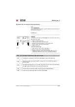
Cleaning

NOTICE

Contrary to the instructions given in Chapter “General service work” in the 
Operator’s Manual of the machine, neither clean the machine with a bristle 
brush nor with a steam jet or a high-pressure cleaner!

If cleaning the machine with these means cannot be avoided, check 
the wax coating very carefully and have it renewed or reapplied as 
required.

If you replace components, check whether they are classified as in the 
table “Components coated with anti-corrosive wax” and whether they 
are subject to special treatment before assembly.

Have the sealing checked and repaired at least once a year by 
ELASKON – see the ELASKON servicing pass supplied with the 
machine.

• If the machine is used in corrosive environment over a longer period of 

time, remove the floor mat in the cabin to avoid the accumulation of 
corrosive humidity.

• Thoroughly clean machines that are put out of operation over a longer 

period of time.

• Clean the machine at least once a week. In particular, remove 

corrosive deposits (such as salt crusts) as fast as possible.

• Clean the machine with cold running water preferably.

Summary of Contents for 418-12

Page 1: ...Operator s manual Telehandlers TH627 Machine model 418 12 Version 1 0 Document number 1000390678 Language us This Operator s Manual includes the AEM Safety anual RTF 0907 ...

Page 2: ...and criminal prosecution KRAMER WERKE GmbH keep abreast of the latest technical developments and constantly improve their products For this reason we may from time to time need to make changes to figures and descriptions in this documentation that do not reflect products that have already been delivered and that will not be implemented on these vehicles Technical data dimensions and weights are on...

Page 3: ... and regulations on use 3 6 3 4 Labels 3 26 4 Putting into operation 4 1 Cabin control stand 4 1 4 2 Overview of control elements 4 29 4 3 Overview of indicator lights 4 34 4 4 Preparatory work 4 49 4 5 Starting and stopping the engine 4 58 5 Operation 5 1 Steering system 5 1 5 2 Accelerator actuation 5 7 5 3 Brake 5 10 5 4 Machine travel operation 5 14 5 5 Differential lock 5 21 5 6 Lights signal...

Page 4: ...9 Maintenance of attachments 7 79 7 20 Maintenance of options 7 80 7 21 Camera maintenance optional 7 82 7 22 Exhaust gas cleaning system 7 83 7 23 Machine preservation 7 84 8 Malfunctions 8 1 Diesel engine malfunctions 8 1 8 2 Malfunctions of the travel drive 8 3 8 3 Disorders in the work hydraulics 8 4 8 4 Malfunctions of the electrical system 8 5 8 5 Malfunctions in the air conditioning system ...

Page 5: ...employed to determine the environmentally polluting noise emissions for use of the machines in question in the open air Notified body involved in procedure DGUV Test Prüf und Zertifizierungsstelle DGUV testing and certification center EU identification number 0515 Building Trade Department Landsberger Straße 309 D 80687 Munich Applicable harmonized standards EN 13309 2010 EN 1459 1 2017 EN 1459 5 ...

Page 6: ...ements regarding safety and health stated in the EC Directives 2006 42 EC 2000 14 EC 2014 30 EU EN 13309 2010 EN 1459 1 2017 EN 1459 5 2015 Authorized representative for the compilation of technical documentation Kramer Werke GmbH Product Development Wacker Neuson Str 1 D 88630 Pfullendorf Pfullendorf the _ _ _ _ _ _ _ _ M Arndt Head of product development Kramer Werke GmbH Designation Telehandler...

Page 7: ...ning in safe working on and with the machine The basis for this in the Federal Republic of Germany is the DGUV principle 308 009 Get informed on and follow the legal regulations of your country recommend repeating the training sessions at regular intervals The buyer operating company is responsible for ensuring that any additional safety regulations applicable in the country of use of the machine ...

Page 8: ...erator s manual We keep abreast of the latest technical developments and constantly improve our products For this reason we may from time to time need to make changes to figures and descriptions in this documentation that do not reflect products that have already been delivered and that will not be implemented on these machines Technical data dimensions and weights are only given as an indication ...

Page 9: ...munity EGR Exhaust Gas Recirculation exhaust gas recirculation system for combustion gases emission reduction EN European Norm etc et cetera from Latin and so forth EU European Union poss possibly FOPS Falling Object Protective Structure FeV Driver s license ordinance FZV Vehicle Admission Ordinance if nec if necessary ISO International Organization for Norming LED Light Emitter Diode light diode ...

Page 10: ...eliable control but also on maintenance and servicing of the machine This is why regular maintenance and servicing is absolutely necessary Information Repair work maintenance or modifications may only be performed by specifically trained technical personnel or by an authorized service center In particular those specified in the maintenance chapter Information on maintenance and Maintenance overvie...

Page 11: ...ed Consequences in case of non observance Avoidance of injury or death WARNING WARNING identifies a situation that can cause death or serious injury if it is not avoided Consequences in case of non observance Avoidance of injury or death CAUTION CAUTION identifies a situation that can cause injury if it is not avoided Consequences in case of non observance Avoidance of injury NOTICE IMPORTANT iden...

Page 12: ... obligated not to put into operation or operate a damaged or malfunctioning vehicle If a damage or malfunction occurs during operation put the vehicle out of operation immediately and secure it against restart Have all malfunctions jeopardizing the safety of the operator or other persons immediately repaired by an authorized service center Do not put the vehicle into operation or operate it after ...

Page 13: ...paired only by an authorized service center Required knowledge of operator The operator is responsible for other persons Avoid any operational mode that might be prejudicial to safety The specific national driving license is required The vehicle may only be operated by authorized and safety conscious persons who are fully aware of the risks involved in operating the vehicle The operator and owner ...

Page 14: ...rate the vehicle only with the seat belt fastened and only from the place provided for this Check the condition and the fastening of the seat belt Have malfunctioning seat belts and mounting hardware replaced by an authorized service center Before starting work adjust the seating position so that all control elements can be reached and fully operated Perform the personal adjustment at machine stan...

Page 15: ...ion for example risk of carbon monoxide poisoning Use existing visual aids to stay aware of the danger zone In conditions of darkness and poor visibility switch on existing work lights and ensure that motorists are not blinded by these lights If the existing lights of the vehicle are not sufficient for performing work safely ensure additional lighting of the job site There is an increased risk of ...

Page 16: ...art the engine only according to the Operator s Manual Observe all warning and indicator lights Do not use any liquid or gaseous starting aids for example ether or starting fuel Machine operation Start and operate the vehicle only with the seat belt fastened and only from the place provided for this Put the vehicle into operation only if visibility is sufficient have another person guide you if ne...

Page 17: ...he registration documents When transferring the machine on public roads the attachment must be brought into transport position and emptied if necessary The mounted attachment must be equipped with the mandatory lighting and protective devices Take measures against unintentional operation of the operating hydraulics If the vehicle has different steering modes ensure that the mandatory steering mode...

Page 18: ...ing and removing a load Wear protective clothing and equipment when fastening guiding and removing loads for example a hard hat safety glasses protective gloves safety boots Do not place lifting and fastening gear over sharp edges or rotating parts Loads must be fastened so as to prevent them from slipping or falling Move loads only on horizontal level and firm ground Move loads close to the groun...

Page 19: ...er the load Stop the vehicle immediately and stop the engine if persons enter the danger zone Use the machine for lifting gear applications ONLY if the mandatory lifting gear for example a joint rod and load hook and safety equipment for example optical and acoustic warning devices hose burst valve stability table is installed and functional Use only lifting and fastening gear certified by a test ...

Page 20: ...ting behavior the operator must be familiar with this and act accordingly Bear in mind the machine s steering mode and the trailer s turning circle Before hitching unhitching the trailer secure it to prevent it from rolling away for example with the parking brake suitable wheel chocks There must be nobody between the vehicle and the trailer when hitching a trailer Hitch the trailer onto the vehicl...

Page 21: ...ly Before starting work operate the attachment to check that it works correctly Before putting the attachment into operation ensure that nobody is in danger Lower the attachment to the ground before leaving the operator s seat Removing and fitting attachments Before uncoupling or coupling hydraulic connections Stop the engine Release the pressure of the work hydraulics Picking up and lowering atta...

Page 22: ... Manual to avoid damage to the vehicle Observe the national regulations for example the light regulations when towing on public roads sites Towing Seal off the danger zone Ensure that no one is near the sling or towing cable The safety distance is equal to 1 5 times the length of the towing equipment Have a recovery service or an authorized service center tow the vehicle away A tractor vehicle of ...

Page 23: ... within sight or sound of him Observe all movements of the machine and lifting gear Secure the vehicle against unintentional movement Raise the vehicle only after it is safely attached and the person attaching the vehicle has given his approval Use only the slinging points provided for fastening the lifting gear for example cables belts Do not attach the machine by twining the lifting gear for exa...

Page 24: ...lifting and fastening gear that is dirty damaged or not of sufficient size In order to secure the machine on the platform use only the fastening points provided for this purpose Ensure that nobody is in or on the vehicle during transportation Observe the national regulations for example Merkheft Erdbau maschinen leaflet on earth moving machines of the German employers liability insurance associati...

Page 25: ...o cool down before touching components Personal safety measures Avoid any operational mode that might be prejudicial to safety Wear protective clothing and equipment for example a hard hat protective gloves safety boots Tie back long hair and remove all jewelry If maintenance on a running engine cannot be avoided Only work in groups of two Both persons must be authorized and trained for the operat...

Page 26: ...nder a raised machine attachment support the machine attachment for example with a lift platform trestles ensuring safety and stability Hydraulic cylinders or jacks alone do not sufficiently secure a raised vehicle attachment Measures for performing maintenance Perform only the maintenance described in this Operator s Manual All work that is not described in this operator s manual must be performe...

Page 27: ...e parts Protective structures The cabin rollbar and protective screen are tested protective structures and may not be modified for example no drilling bending welding Perform a visual check according to the maintenance plan for example check the fastenings for damage If damage or defects are detected have them immediately checked and repaired by an authorized service center Have retrofitting work ...

Page 28: ...eaks and visible damage Splashed oil can cause injury and fire Leaking hydraulic and compressed air lines can cause the full loss of the brake effect Have damage and leaks immediately repaired by an authorized service center Have hydraulic hoses replaced by an authorized service center within stipulated intervals even if no visual defects can be detected Electrical system Use only fuses with the s...

Page 29: ...ath Keep the area around the exhaust system free of flammable materials Check the engine and fuel system for leaks for example loose fuel lines Don t start or let the engine run in case of leaks Breathing the exhaust fumes causes death very quickly Engine exhaust contains gases you cannot see or smell for example carbon monoxide and dioxide Operate the machine only on appropriately ventilated area...

Page 30: ...luted environment dust vapors smoke asbestos work only with appropriate personal protective equipment for example with a breathing mask Fire hazard Fuel lubricants and coolants are flammable Do not use flammable detergents Keep the area around the exhaust system free of flammable materials There is an increased risk of fire from hot machine parts and exhaust gases Stop and park the vehicle only in...

Page 31: ...ured accordingly If live supply lines are touched nevertheless Do not leave touch the cabin Faraday cage If possible drive the vehicle out of the danger zone Warn others against approaching and touching the machine Have the live wire de energized Do not leave the machine until the supply lines that have been touched or damaged have been safely de energized Working near non electric supply lines Be...

Page 32: ...ectors Do not wear ear protectors during machine travel on public roads sites Cleaning Risk of injury from compressed air and high pressure cleaners Wear appropriate protective clothes Do not use any dangerous and aggressive detergents Wear appropriate protective clothes Operate the machine only in a clean condition Remove all dirt snow and ice from climbing aids for example from the handholds foo...

Page 33: ...eadlight with turn indicator 4 Additional marker lights left right optional 5 Rear mirror left right with additional mirror 6 Front right working light option 7 Front numberplate fixture option 8 Rotating beacon option 9 Front left work light 10 Front wiper 11 Boom working lights option 12 Rear loading lug left right 13 Turn indicator brake rear light 14 Fuel tank filler inlet 15 Rear wiper 16 Lef...

Page 34: ...ame 24 Towing device or ball hitch optional or automatic ball hitch optional 25 PTO drive optional 26 Connections Hydraulically activated trailer brake optional 27 Socket trailer lights option 28 Eye hook1 for installing removing the cabin 29 Front edge protection 30 Hydraulic connections 3rd control circuit additional control circuit as an option 31 Door lock 32 Fuel cap 33 Wheel chock 34 Touch b...

Page 35: ...ntroduction 3 Models and trade names overview The machine is identified by two designations Type designation Stamped on the type label see Vehicle on page 3 36 Trade name affixed outside on the vehicle Telehandler model Trade name 418 12 TH627 ...

Page 36: ...tandard 97 68 EC Automotive drive progressive hydrostatic axial piston gearbox Maximum speed 20 km h 12 4 mph series Maximum speed 30 km h 18 6 mph option Hydraulic power steering with emergency steering features Front and rear planetary steering axles rigid front axle rear axle with oscillation Service brake brake disc on rear axle drive shaft brake effect on front axle via cardan shaft Parking b...

Page 37: ... valve also the hydrostatic steering The oil flow of the pump depends on the diesel engine speed When the machine is in operation the entire diesel engine output can be transmitted to the gear pump for the work hydraulics and steering This is made possible by a so called inching valve that responds as soon as the brake inching pedal is used reducing or cutting off power input of the drive Therefor...

Page 38: ...eral Certification for Vehicles Germany or the Data Confirmation Germany Get informed on and follow the legal regulations of your country Information For safety reasons the vehicle is equipped with a start up lock in all EU member states and in Australia The vehicle can only be operated if the operator has sat down on the operator s seat If the operator seat is left at a standstill or with the han...

Page 39: ...nly depend on your reliable control but also on maintenance and servicing This is why regular maintenance and servicing is absolutely necessary see chapter 7 Cleaning and maintenance on page 7 20 Information Repairs maintenance or modifications may only be performed by an authorized service center Insist on using original spare parts for repairs The machine s permits certifications registrations e...

Page 40: ...traffic in the Federal Republic of Germany The set up conditions permitted attachments as well as the corresponding requirements can be found in the ABE general operating permit or the data confirmation for vehicles with permission as a self propelled work machine in Germany see Use of attachments on page 3 13 Attachments without a General Certification for Vehicles Germany or Data Confirmation re...

Page 41: ...ilure to follow warning instructions on the machine and in the operator s manual Maintenance and repair work by untrained personnel Machine modifications without proper authority Fastening installation of additional equipment that has not been certified released Use of non original spare parts Use for spraying applications Use for forestry applications Use as a carrier machine for equipment that h...

Page 42: ...achine Driving license category L Self propelled work machines up to 25 kph Agricultural or forestry tractors up to 40 kph with trailer 25 kph Driving license category C Motor vehicles with over 3500 kg gross weight rating with trailers up to 750 kg Driving license category C1 Motor vehicles between 3500 and 7500 kg gross weight rating with trailers up to 750 kg Driving license category CE Motor v...

Page 43: ... place where the machine is used As evidence of the inspection affix an inspection label on the machine for evidence see example on the left The inspection tag can be acquired from the relevant inspection authorities Bear in mind that all work equipment is inspected not only the machine but also all technical auxiliary means tools and attachments Work equipment is defined as all tools attachments ...

Page 44: ...n compliance with DIN 13 164 sheet 1 Get informed on and follow the legal regulations of your country Warning identification of machine on public roads option According to 52 clause 4 1 of StVZO German road traffic regulations from 01 10 1998 onward machines that are used on public roads for the construction maintenance and cleaning of roads or facilities can be fitted with the red and white warni...

Page 45: ...rpose Warranty rights shall not apply if uncertified attachments or attachments from other manufacturers are installed Machine travel on public roads with a full bucket is prohibited With a mounted attachment the possible line of sight impairment must also be observed see Field of vision during road travel on page 4 6 and Field of vision during work operation on page 4 7 Information The applicatio...

Page 46: ...n the quickhitch and the specific attachments Information The use of attachments that are not listed for the corresponding quick hitch systems must be tested and documented for compliance stability inspection according to the EC machine directive or the standard EN 1459 by an authorized specialized workshop in the EU member states load bearing capacity diagram see chapter 5 Fitting attachments fro...

Page 47: ...or during work operation and take appropriate action 2 Attachments are only permitted for the KRAMER quickhitch facility 3 Machine travel on public roads is only certified if a front edge protection is installed over the entire width of the bucket 4 Capacity struck according to ISO 7546 capacity heaped 5 With screwed on bucket blade 6 Only permitted for public traffic in conjunction with additiona...

Page 48: ...silage straw and manure Gate opener 6 11 1000278984 Opening and closing specially equipped up and over doors 1 Pay attention to the safe load indicator during work operation and take appropriate action 2 Attachments are only permitted for the KRAMER quickhitch facility 3 Machine travel on public roads is only certified if a front edge protection is installed over the entire width of the bucket 4 C...

Page 49: ...fork6 7 8 10002478179 1200 47 2 Load diagram Picking up and transporting pallets 1000363244 1200 47 2 Load diagram 1 Pay attention to the safe load indicator during work operation and take appropriate action 2 Attachments are only permitted for the KRAMER quickhitch facility 3 Capacity struck according to ISO 7546 capacity heaped 4 Machine travel on public roads is only certified if a front edge p...

Page 50: ...tact your dealer if you require more information on the quickhitch and the specific attachments Information The use of attachments that are not listed for the corresponding quick hitch systems must be tested and documented for compliance stability inspection according to the EC machine directive or the standard EN 1459 by an authorized specialized workshop in the EU member states load bearing capa...

Page 51: ...out teeth 1 44 50 8 Picking up transporting and loading lightweight material 1 13 p 70 5 10002531085 2200 86 6 without teeth 1 58 55 8 1 0 p 62 4 Non approved attachments for machine travel on public roads Federal Republic of Germany Pallet forks6 7 1000363308 1200 47 2 Load diagram Picking up and transporting pallets Bucket super lightweight material 1000252432 2500 98 4 without teeth 1 80 63 5 P...

Page 52: ...al protection Please contact your dealer if you require more information on the quickhitch and the specific attachments Information The use of attachments that are not listed for the corresponding quick hitch systems must be tested and documented for compliance stability inspection according to the EC machine directive or the standard EN 1459 by an authorized specialized workshop in the EU member ...

Page 53: ...lic roads Federal Republic of Germany Pallet forks3 4 1000363305 1200 47 2 Load diagram Picking up and transporting pallets 1 Pay attention to the safe load indicator during work operation and take appropriate action 2 Attachments are only permitted for the EURO quickhitch facility 3 Application only with attachment specific load diagram 4 See the Operator s Manual of the attachment for putting th...

Page 54: ...ental protection Please contact your dealer if you require more information on the quickhitch and the specific attachments Information The use of attachments that are not listed for the corresponding quick hitch systems must be tested and documented for compliance stability inspection according to the EC machine directive or the standard EN 1459 by an authorized specialized workshop in the EU memb...

Page 55: ...00360255 5100024531 Load diagram Picking up and transporting pallets 1000360819 5100018703 1000360820 5100018704 1000360831 5100018705 Bucket 1000360253 5200023772 Loosening picking up transporting and loading of loose or solid material 1000360251 5200003427 1000360254 5200016975 1000360252 5200015856 1 Pay attention to the safe load indicator during work operation and take appropriate action 2 At...

Page 56: ... are subsequently modified or replaced the operation license and the warranty become void In addition to the Operator s Manual observe and instruct the operator in all other generally applicable legal and other mandatory regulations relevant to accident prevention and environmental protection Please contact your dealer if you require more information on the quickhitch and the specific attachments ...

Page 57: ... on public roads in the Federal Republic of Germany In the case of an approval as a self driving machine only attachments may be carried along if they are registered in the General Certification for Vehicles Germany See page 3 13 No attachments are registered for the three point mount Attachments without a National Type Approval Germany or Data Confirmation require a special registration made out ...

Page 58: ...3 26 BA 418 12 1 0 418_12_3_Einleitung fm 3 Introduction 3 4 Labels Overview Signage Europe Left side of machine Fig 3 30 20 ...

Page 59: ...BA 418 12 1 0 418_12_3_Einleitung fm 3 27 Introduction 3 Right side of machine Fig 4 30 20 ...

Page 60: ...3 28 BA 418 12 1 0 418_12_3_Einleitung fm 3 Introduction Front of machine Fig 5 ...

Page 61: ...BA 418 12 1 0 418_12_3_Einleitung fm 3 29 Introduction 3 Rear of machine Fig 6 30 20 ...

Page 62: ...3 30 BA 418 12 1 0 418_12_3_Einleitung fm 3 Introduction Overview Signage USA Australia Outside left of the vehicle Fig 7 ...

Page 63: ...BA 418 12 1 0 418_12_3_Einleitung fm 3 31 Introduction 3 Outside right of the vehicle Fig 8 ...

Page 64: ...3 32 BA 418 12 1 0 418_12_3_Einleitung fm 3 Introduction Inside the cabin Fig 9 ...

Page 65: ...BA 418 12 1 0 418_12_3_Einleitung fm 3 33 Introduction 3 Engine compartment interior Fig 10 ...

Page 66: ...3 34 BA 418 12 1 0 418_12_3_Einleitung fm 3 Introduction Outside front of the vehicle Fig 11 ...

Page 67: ...BA 418 12 1 0 418_12_3_Einleitung fm 3 35 Introduction 3 Outside rear of the vehicle Fig 12 ...

Page 68: ...Description Entry 30 Vehicle category1 1 Only for EU tractor approval T1a 21 EU type approval number1 22 Identification number machine chassis number WNK41812xxxxx0015 08 Maximum permissible weight kg 7500 kg 16 534 7 lb 23 Front axle weight rating kg 4480 kg 9876 7 lb 24 Rear gross axle weight rating kg 4480 kg 9876 7 lb B 1 Gross unbraked trailer weight rating T 1 drawbar trailer kg T 2 rigid dr...

Page 69: ...Under consideration and observance of the permissible gross axle weight ratings as well as the permissible gross weight rating 01 Machine designation TELESCOPIC LOADER or TRACTOR 03 Machine model 418 05 Variant 418 12 04 Output kW 55 4 kW 74 hp 07 Transport weight kg 09 Maximum payload kg 06 Gross operating weight kg 13 Year of construction 2018 Fig 15 05 18 19 22 08 10 11 13 B Item Description En...

Page 70: ...vehicle frame It is also located on the type label The identification number serial number shown is just an example Cabin number The nameplate arrow is located in the cabin at the bottom left on the B bar W N K 41812 X X X X X 0015 Fig 16 Manufacturer works Vehicle model version Standard specific test number Factory coding Sequential number Exam ple A Fig 17 ...

Page 71: ... 1 Reference year for compliance with standards 2 Output kW hp 3 Displacement of the engine L 4 Entry of particulate emission g kWh 5 Serial number engine family 6 Emission Control System ECS 7 Fuel with low sulfur content 8 Specification of the fuel injection timing PPMS 9 Pressure opening injection valve bar 10 Date of manufacture Reading example Information on the nameplate B 1 Engine model 2 S...

Page 72: ...chine The type label arrow is located on the variable displacement motor housing flanged on the transfer gearbox Transmission number Seen on lower side of machine The type label arrow is located on the gearbox housing flanged on the front axle Front and rear axle numbers Seen on lower side of machine The type label arrow is located on the axle carrier Rear axle on the left in travel direction Fron...

Page 73: ...tely replace damaged warning and notice signs with new ones Warning label Cabin eye hooks The eye hooks on the cabin are for removing the cabin only and may not be used for crane lifting the machine Located on the cabin roof 4x Warning label General indication of danger Caution All persons must stay clear of the danger zone of the telehandler Located at front left and right of vehicle frame and at...

Page 74: ...ide the cabin Warning label Remove the ignition key Caution Remove ignition key before performing inspections and maintenance on the machine Read the service manual before performing maintenance Repair work may be performed by an authorized workshop only Located on the pillar on the right inside the cabin Warning label Seat belt and vehicle stability Operate the machine only from the operator seat...

Page 75: ... not open radiator is hot and under pressure Open the radiator only after the coolant has cooled down Open the cover carefully to the first stop notch to allow the pressure to escape Wear protective gloves and clothing Located in the engine compartment next to the radiator coolant Warning label Danger in case of broken window on the right In order to avoid a crushing or accident hazard stop the ma...

Page 76: ...ing Use only the diesel fuels indicated DIN EN 590 EU ASTM D975 94 USA Do not use diesel fuel with additives If other fuels are used warranty rights shall not apply in case of diesel engine damage guarantee Fixed behind the cabin on the left near the filler neck of the fuel tank Notice sign the operator s controls of the joystick three point suspension optional Operation see chapter 5 Three point ...

Page 77: ...onic engine control the battery main switch may not be immediately unscrewed from the ratchet mechanism after shutting off the engine Fixed in the engine compartment near the battery main switch see chapter 4 Battery master switch on page 4 22 Information label Filler opening for hydraulic oil A Hydraulic oil B Biodegradable hydraulic oil Located next to the filler opening hydraulic oil reservoir ...

Page 78: ...hat are indicated on the label Located inside the cabin Label low speed control option A maximum speed B standstill Fixed near the joystick right in the cabin see chapter 5 Low speed control option on page 5 19 Label manual throttle option A Increase the engine speed B Reduce the engine speed Fixed near the joystick right in the cabin see chapter 5 Manual throttle option on page 5 8 Label Fresh ai...

Page 79: ...from handling of personnel with this machine Lifting or transporting persons on the machine in the bucket or on the pallet forks is prohibited No personal platforms regardless of the type may be attached to the vehicle Affixed front on the loader unit and in the cabin on the right side window Hazardous sign diesel fuel Danger of suffocation from exhaust fumes of the diesel fuel in poorly ventilate...

Page 80: ... the vehicle into service always check the functions of the individual joysticks with a brief actuation Affixed in the cabin on the window on the right Danger sign running engine No running engine in closed areas Exhaust gas can kill you in minutes Affixed in the cabin on the window on the right Danger sign Electrical open wires Contacting power lines will result in death or serious injury Do not ...

Page 81: ...l work movements as soon as a person enters these areas Affixed near the wheels 4x Warning label High pressure in the hydraulic lines Hydraulic oil escaping under pressure can penetrate the skin and cause serious injuries Relieve pressure before disconnecting hydraulic lines Keep your distance from leaks Do not search for leaks with your hand Liquid penetrating into the skin must be treated by a d...

Page 82: ...t induce vomiting WARNING danger of explosion The battery acid reacts with the surrounding metals and produces hydrogen There is a danger of explosion Keep metal objects away from the battery terminals Attach protective cover to the positive terminal of the battery Install and remove jump start and perform maintenance on the battery only in well ventilated premises or outdoors Avoid unprotected li...

Page 83: ... oil to cool down Do not open the hydraulic oil reservoir immediately after stopping the engine Affixed near the filler neck of the hydraulic oil tank on the right Warning label General indication of danger Caution All persons must stay clear of the danger zone of the telehandler Located at front left and right of vehicle frame and at rear of machine Warning label Danger in case of broken window o...

Page 84: ...om elevated components Affixed on the loader unit Warning sign Suspended loads Crushing hazard Lowering the loader unit or a falling load could cause death or serious injuries All persons must stay clear of the danger zone of the telehandler Immediately stop work if people enter the danger area Keep other persons away during operation Affixed in the cabin on the window on the right Warning sign El...

Page 85: ... protective structure FOPS control procedures The cabin only offers a protective function if the machine has not been modified changed transformed or converted There is a crushing and accident hazard No welding drilling bending on the protective ROPS FOPS structure A damaged protective structure must be checked and maintained by an authorized service center for its protective function Affixed in t...

Page 86: ... your seat belt Read the Operator s Manual before lifting the machine Affixed on the central pillar on the right in the cabin Warning sign Keep a minimum safety distance Rollover hazard can cause serious injury or death All persons must stay clear of the danger zone of the telehandler Immediately stop work if people enter the danger area Keep other persons away during operation Use all rearview mi...

Page 87: ...hments 8 Do not use machine in space with explosive dust or gases or with flammable material near exhaust 9 Make sure all shields are in place and securely fastened 10 Do not convey any people 11 Never modify equipment 12 Check for underground and overhead lines before taking the vehicle into service 13 Check the position of the attachment for travel direction before operating the drive system 14 ...

Page 88: ...ase of an accident with the machine the battery can be disconnected immediately emergency stop switch For the protection of the maintenance personnel during maintenance protection against unintentional machine start As an immobilizer when parking the machine overnight anti theft protection In order to avoid a malfunction in the electronic engine control the battery main switch may not be immediate...

Page 89: ...l elements design A Operation see chapter 5 Joystick joystick on page 5 42 Located on the right on the side window Label control elements joystick design USA Operation see chapter 5 Joystick joystick on page 5 42 Located on the right on the side window Label control elements design B Operation see chapter 5 Joystick joystick on page 5 42 Located on the right on the side window Fig 87 A B C Fig 88 ...

Page 90: ...th a sulfur content of 15 mg kg US UNITS or less Affixed near the filler neck of the fuel tank Notice sign Shut off the engine The engine is started by turning the starting key to the right The engine stops if the ignition switch key is turned to the left with the engine running see chapter 4 Starting the engine on page 4 60 Affixed in the cabin on the ignition lock Notice sign Apply the hand brak...

Page 91: ...standstill Fixed near the joystick right in the cabin see chapter 5 Low speed control option on page 5 19 Label manual throttle option A Increase the engine speed B Reduce the engine speed Fixed near the joystick right in the cabin see chapter 5 Manual throttle option on page 5 8 Label Fresh air recirculated air circuit for air conditioning system option A Recirculated air mode B Fresh air mode At...

Page 92: ... labels are available from their sales partner via the spare parts service The load bearing diagramsA are located in the holder on the right at the side window Depending on the vehicle orientation the folding panels consist of for example Tire pressure table Load diagram for pallet forks Load bearing diagram for crane jib Tire pressure table diagram example The sign includes a list of approved tir...

Page 93: ...he pallet fork and the crane jib Attached to the right on the side window Information The load diagram is valid only for applications with the released attachments and corresponding tire sizes Pay attention to the specific load diagrams of other attachments used see chapter 5 Fitting attachments from other manufacturers option on page 5 78 Fig 103 ...

Page 94: ... known to the State of California to cause cancer and birth defects or other reproductive harm Ź Always start and operate the engine in a well ventilated area Ź If in an enclosed area vent the exhaust to the outside Ź Do not modify or tamper with the exhaust system Ź Do not idle the engine except as necessary For more information go to www P65warning ca gov diesel WARNING Cancer and Reproductive H...

Page 95: ...pproved for forestry applications A cabin damaged deformed in an accident may not be repaired but must be replaced by an authorized service center It is prohibited to drill through elements of the cabin or to weld or separate elements of the cabin as this work changes the cabin and it therefore no longer complies with the officially approved model roll over protective structure FOPS Attaching an a...

Page 96: ...rushing when closing Always lock the cabin doors Use the handholds for closing Information The machine has a one key system All the locks of the cabin ignition lock engine cover fuel tank hydraulic tank and tool kit are opened and locked with the key of the vehicle Opening the cabin from the outside 1 Pull handle A outward Opening the cabin from the inside 1 Pull handle B up A Fig 105 Fig 106 B ...

Page 97: ...dow in the driver s door completely 1 Turn the lever to the rear from the locked position A 2 Fold the side window completely to the outside and lock into place in arrester B Information Lubricate arrester B at regular intervals Lock the side window in the driver s door 1 Loosen the lever from the locked positionA 2 Close the side window completely and turn the lever to the locked position A Fig 1...

Page 98: ... locked position arrow C 2 Close the rear window and lock with the lever in the direction of the arrow D Rear window emergency exit In case of an emergency the rear window can be used for exiting from the cabin if the door can no longer be used Exit the cabin in an emergency as follows 1 Stop the diesel engine 2 Switch off all electric consumers and remove the ignition key 3 If possible ask for he...

Page 99: ...e window Failure to observe this can cause serious injury or death If the vehicle is damaged do not operate it or immediately bring it to a standstill during operation 1 Immediately bring the vehicle to a standstill if the side window is damaged 2 Keep a safe distance to the loader unit as you lower it to the ground carefully see chapter 5 Raise lower the loader unit extend and retract the telesco...

Page 100: ...port to the site of use Information The field of vision has been determined according to ISO 5006 The adjacent graphic describes the existing restrictions in line of sight within the radius of 12 m 4724 4 in with the retracted telescopic boom with the bucket in the transport position 175 mm 6 9 in The gray highlighted area in sector A as well as in sector F show the lines of sight of the operator ...

Page 101: ...he job site Do not move material with a raised loader unit Only move loaded goods in the transport position A If the line of sight cannot be safely adjusted with the mirrors the operator must take appropriate measures optional camera flagman The operator of the machine always has the sole responsibility for this WARNING Accident hazard due to persons in the danger zone Persons entering the danger ...

Page 102: ...sector B A C E as well as in the sector F show the lines of sight not visible to the operator with the loader unit raised Line of sight restriction in stacking mode to 1 meter s height Information The field of vision was determined according to ISO 5006 road travel and DIN EN 15830 2012 work operation The adjacent graphic describes the existing line of sight restrictions within the radius of 12 me...

Page 103: ...adius of 12 meters 4724 4 in with a retracted telescopic boom and mounted pallet forks with a loader unit with goods raised about 0 5 meters 19 7 in The gray highlighted areas in sector A C and E as well as in sector F show the lines of sight of the operator that are not visible b In the sector C outside of the radius of 12 m 4724 4 in line of sight restriction at the height of 590 mm 23 2 in at t...

Page 104: ...front about 90 to avoid touching the door window 2 Adjust the left rearview mirror The outer edge of the vehicle must be visible in the mirror area X The horizon must be visible in the Y mirror section In the Z section the visible area of the road must be as close as possible to the machine Information When adjusting make sure that the mirror holder is turned far enough forward about 90 in order t...

Page 105: ...oader unit to the transport position 2 Adjust the rearview mirror on the right The outer edge of the vehicle must be visible in the mirror area X The horizon must be visible in the Y mirror section The visible area of the road must reach as close to the vehicle as possible in the mirror area Z Fig 121 X Y Z X Y Z Fig 122 ...

Page 106: ...ible in the Y mirror section In the mirror area Z the entire right rear wheel must be visible Adjusting the rear mirrors option Information The rear view mirror in the rear is required in conjunction with a ball hitch optional and must be used when coupling and decoupling 1 Bring the rear view mirror in the rear optional into position so that the rear of the vehicle with the ball hitch can be full...

Page 107: ...ebnahme fm 4 13 Putting into operation 4 Adjusting the rearview mirrors option Adjust the rearview mirror so that you can see as much of the traffic behind the vehicle as possible and as little of your own interior as possible Fig 126 ...

Page 108: ...nitoring non visible or poorly visible areas on the vehicle A Camera fastened to the right mirror holder front and or B camera on the vehicle rear C Color monitor in the cabin Information For more information about the operation and adjustment of the camera see 5 153 for maintenance see page 7 82 for technical data see page 9 12 C B A Fig 127 ...

Page 109: ...The area Y up to the area X next to the right front wheel The area forward Z at least 12 m 4724 4 in or beyond Camera line of sight on the vehicle rear 1 Adjust the visible range of the camera so that the following areas can be seen on the screen Right outside X the area behind the right rear wheel Left outside Y the area behind the left rear wheel To the rear Z the area up to the rear of the vehi...

Page 110: ...ange of the operator seat Modifying the operator seat by using spare parts other than original for example can cause the approval given for the operator seat to be void Functions that are important for safety can be affected If the seat functions do not work as usual seat suspension for example contact a service center immediately for repair Information For safety reasons the vehicle is equipped w...

Page 111: ...er weight 3 Turn lever D counterclockwise 4 Read the weight on the display C Information The weight indicator C shows the set operator weight kg Backrest adjustment 1 Sit down on the operator seat 2 Pull lever A upward and at the same time lean back to push the backrest into the required position 3 Lock the lever A into place Horizontal adjustment 1 Sit down on the operator seat 2 Pull lever B upw...

Page 112: ...ositions A Lumbar support B Backrest adjustment for description see page 4 17 C Suspension of the operator seat D Weight and height adjustment E Horizontal suspension F Longitudinal adjustment for a description see page 4 17 The weight and height setting is variably adjusted with the air assistance of an air compressor There are two settings for the automatic weight adjustment The second setting a...

Page 113: ...ertain conditions for example driving with a trailer This enables the operator seat to dampen shocks in travel direction Position a horizontal suspension ON Position b horizontal suspension OFF Adjustable seat suspension damper option The operator can adjust the seat suspension to his own requirements and to different work conditions Four levels ranging from soft to hard are possible Lever C in po...

Page 114: ...ccident hazard due to damaged or dirty seat belt A damaged or dirty seat belt can cause serious injury or death Keep the seat belt and buckle clean Check the seat belt and buckle for damage Have a damaged seat belt and buckle replaced by an authorized service center Have the seat belt immediately replaced after every accident and the load bearing capacity of the fastening points and seat fixtures ...

Page 115: ...pull test The seat belt must not be twisted and must run tightly over the hips Unfastening the seat belt 1 Hold the seat belt 34 2 Press red button C on buckle B Latch A is released from buckle B 3 Slowly return the seat belt to the retractor Information When pulled slowly the automatic seat belt offers full freedom of movement It locks however during abrupt braking The automatic seat belt may als...

Page 116: ...the notice sign B NOTICE An external auxiliary heater option cannot be operated if the battery master switch is removed In order to avoid damage to the auxiliary heating optional first disconnect the power circuit with the battery main switch once the after running of the heater has ended Switch off the battery master switch 1 First stop the diesel engine with the ignition key 2 Wait at least 30 s...

Page 117: ...thorized service center Operate the fire extinguisher according to the instructions printed on the fire extinguisher Information In order to ensure the full serviceability of the fire extinguisher Have the fire extinguisher checked at regular intervals and refilled see inspection tag Only remove the fire extinguisher from the cab in an emergency After the fire extinguisher has been used have it fi...

Page 118: ...tch on the machine lights see chapter 5 Parking lights low beam on page 5 23 Coding is performed by inserting the master key in the ignition lock and by turning it to position 1 for a maximum 5 seconds After the master key has been returned to position 0 and removed you have 15 seconds for inserting a key that requires coding It must be inserted in the ignition lock and turned to position 1 in ord...

Page 119: ...r the ignition key is inserted in the ignition lock 2 Start the engine see Starting the engine on page 4 60 The immobilizer is disabled as long as the engine runs Deleting coded keys Deleting coded keys is necessary whenever a coded key is lost All coded keys are deleted during deletion After deletion has been performed all existing keys can be recoded 1 Switch on the side marker lights 2 For the ...

Page 120: ...s function avoids finding the correct key by chance by trying different keys Valid keys are accepted only after 15 minutes and after the position 0 of the ignition lock has been detected This avoids testing keys without actuating the mechanical starter for example by moving the starter to position 1 by force Interruptions of the supply line or other control lines do not disable the immobilizer or ...

Page 121: ...ration Heating elements warm up the hydraulic oil in the hydraulic oil reservoir The hydraulic oil circuit can only be thoroughly warmed up if the preheating is connected over a longer period of time The vehicle plug receptacle B 230 V or 110 V for the heater is located on the bracket of the air filter The special cable A for the mains plug receptacle is included in the standard package of the opt...

Page 122: ...paraffin crystals forming which otherwise clog the fuel filter at low temperatures The fuel preheater is automatically activated when ignition is switched on Information A heating element in the fuel line between the tank and the fuel pre filter is automatically switched on by a temperature sensor at temperatures below 10 C ...

Page 123: ...s This chapter describes the controls and contains information on the function and the handling of the indicator lights and controls in the cabin The pages stated in the overview table refer to the operation of the corresponding control elements You can unfold the pages for a better overview Putting into operation Inside of cabin overview ...

Page 124: ...ics 4 56 5 15 5 22 5 42 5 54 5 58 5 66 19 Fresh air filter cabin 7 68 20 Loudspeakers option 21 Joystick orange manual throttle option 5 8 22 Joystick green Proportional Three point receptacle lift lower optional 5 143 23 Joystick blue low speed control option 5 19 24 Joystick Reversing valve for choosing the types of steering 5 2 25 Control panel keypad Auxiliary control circuits optional 4 32 26...

Page 125: ...ptional 4 4 42 Hazard warning system red 5 29 43 Left hand side switch panel 4 32 44 Multifunction lever Indicator high beam low beam windscreen wiper horn 5 23 5 32 45 Brake fluid reservoir 7 75 46 Parking brake 5 12 47 Switch console heating ventilation 5 34 48 Front wiper 5 32 49 Radio aerial option Overview of control elements in cabin Page Overview indicating instruments switch consoles joyst...

Page 126: ...ake 4 35 5 12 7 74 68 Warning light red Coolant level 4 35 7 44 69 Warning light red Temperature of the diesel engine 4 35 7 42 70 Indicator light green differential lock 4 35 5 22 71 Not assigned 72 Indicator light blue high beam 4 35 5 24 Oil volume adjustment optional page 73 Touch button Menu selection back 5 112 74 Touch button Menu selection 3rd control circuit lock unlock 5 112 75 Touch but...

Page 127: ...liary control circuit continuous operation right direction of rotation optional 5 138 104 Touch button green Close auto hitch coupling optional 5 130 105 Touch button green Unlock three point receptacle PTO drive optional 5 143 106 Latching touch button yellow Operation PTO drive optional 5 150 107 Touch button green Lower the tipper optional 5 135 108 Touch button green Rear auxiliary control cir...

Page 128: ...n right left turn indicators on rear attachment Flashes intermittently when the turn indicators are used and a front or rear attachment is connected electrically Indicator light yellow control unit controller Illuminates if an error comes from the engine controller or the cabin controller see chapter 8 Overview of error codes of diesel engine electronics on page 8 7 and Overview of error codes of ...

Page 129: ... parking brake Illuminates when the parking brake is applied Indicator light yellow coolant level Illuminates if the coolant level in the radiator is too low see Cooling system on page 7 42 Indicator light red coolant temperature Illuminates if the maximum permissible coolant temperature is exceeded Information The coolant temperature should be between 80 C 176 F and 105 C 221 F The max permissibl...

Page 130: ...levels are allocated to the display instrument in the digital display 57 Modes of operation of the digital display see page 4 37 Fig 149 57 1st level See page 2nd level See page Main indication 1 4 38 Service indication 4 42 Main indication 2 4 43 Machine status indication HMI 4 44 Machine status indication VCU 4 44 Machine status display ECU 1 ash load 1 Ash loading of the diesel particulate filt...

Page 131: ... jog dial optional Change to the pages of the 1st level by turning the adjusting wheel 77 to the right or left Change to the pages of the 2nd level by pressing the adjusting wheel 77 then turning the adjusting wheel see chapter 5 Oil volume setting with control element jog dial optional on page 5 112 Example of operation Proceed as follows in order to leave the Main indication 1 and to go to the S...

Page 132: ...mbol starts flashing and an acoustic warning sounds every 10 seconds B Indication coolant temperature Indicates the coolant temperature of the radiator Once the maximum permissible coolant temperature is reached the control lamp illuminates 69 in the display instrument and a warning also sounds 7 42 C Symbol Auto hitch coupling optional Appears if the lock of the auto hitch coupling is not secured...

Page 133: ... speed crawler gear 0 7 km h 0 4 3 mph Appears if the operation was activated 5 16 5 130 Symbol turtle speed Operation 0 15 km h 0 9 3 mph Appears if the operation was activated 5 16 Symbol Hare speed Operation 0 20 km h 0 12 4 mph High speed 0 30 km h 0 18 6 mph optional Appears if the operation was activated 5 16 1 2 3 ...

Page 134: ...d 5 15 Symbol Reverse travel direction Appears when the reverse travel direction is activated 5 15 Symbol Neutral travel direction Appears when the travel direction is deactivated 5 15 F Symbol Overload limit Bucket mode Appears if the bucket mode was activated 5 47 Symbol overload limit stacking mode Appears if the stacking mode was activated 5 48 Symbol Overload limit Manual mode Appears if the ...

Page 135: ... Symbol 3rd control circuit in continuous operation optional Appears if the 3rd control circuit is activated in continuous operation 5 59 5 115 Symbol auxiliary control circuit optional Appears if the auxiliary control circuit is activated 5 138 Symbol PTO drive optional Appears if the PTO drive is activated 5 150 Symbol Floating position of the three point receptacle optional Appears if the three...

Page 136: ...l If the next maintenance interval is less than 30 working hours away the warning symbol will be displayed in the main menu for 4 seconds wrench 10 seconds after the diesel engine starts The hours up to the next maintenance interval are displayed in the following order 100 hours of operation 1st maintenance interval 400 hours of operation no maintenance interval 500 hours of operation 2nd maintena...

Page 137: ...zer of the loader unit Appears if the load stabilizer is enabled 5 121 P Symbol Auto hitch coupling optional Appears if the auto hitch coupling is locked 5 130 Symbol Auto hitch coupling optional Appears if the auto hitch coupling is unlocked 5 130 Symbol Raise the tipper optional Appears if the tipper is raised 5 135 Symbol Lower the tipper optional Appears if the tipper is lowered 5 135 Q Symbol...

Page 138: ...achine status indication on engine control unit ECU Not assigned Machine status indication on cabin controller VCU In order to call the machine status indication for the cabin controller press push button 55 repeatedly Contains information data for the cabin controller xxxxxxxxxx Fig 157 HMI xxxxxxxxxx xxxxxxxxxx xxxxxxxxxx xxxxxxxxxx 55 xxxxxxxxxx Fig 158 ECU xxxxxxxxxx xxxxxxxxxx xxxxxxxxxx xxxx...

Page 139: ...error is also saved and can be viewed in the error memory until the next restart The error memory can receive up to 20 different error codes 4 pages X with a maximum 5 error codes Pressing push button 56 takes you to the next page of the error memory Further information see chapter 8 Malfunctions of the electrical system on page 8 5 517551 Fig 160 517900 517901 517902 517903 1 2 3 4 T 56 55 Fig 16...

Page 140: ...repeatedly until you have the required brightness 5 Press touch button 55 in order to leave the display W Digital display settings adjusting contrast 1 Press push button 55 repeatedly until the display settings appear 2 Press touch button 56 until the symbol X is selected 3 Press button 55 Display Y appears 4 Press push button 56 repeatedly until you have the required contrast 5 Press the touch bu...

Page 141: ...h button 55 5 Repeat step 3 for the month day hours and minutes Digital display settings adjusting mph or kph 1 Press push button 55 repeatedly until the display settings appear 2 Press the touch button 56 until the symbol b is selected 3 Press button 55 The display c appears 4 Press push button 56 repeatedly until the required setting is selected and press push button 55 5 Repeat step 3 for the m...

Page 142: ...hydraulics 10 seconds after restarting the diesel engine errors with a continuous warning sound will always be displayed for 4 second until reset or repaired by an authorized workshop Continuous warning sounds are for example If the engine oil pressure falls below 2 bar see Checking the engine oil level on page 7 40 If the engine oil pressure has reached 2 bar 28 4 psi when starting the diesel eng...

Page 143: ...ehicle as you enter and leave it Have damaged climbing aids replaced Information For safety reasons the vehicle is equipped with a start up lock in all EU member states and in Australia The vehicle can only be operated if the operator has sat down on the operator s seat If the operator seat is left at a standstill or with the hand brake released a continuous acoustic warning will sound If the oper...

Page 144: ... parking brake Carrying or transporting accompanying persons in the cabin and or on the machine is prohibited Tell persons to leave the danger zone The machine may only be used in technically perfect condition in accordance with its designated use and the instructions set forth in the operation license the Data Confirmation Germany and in the Operator s Manual and only by persons who are fully awa...

Page 145: ... varying the diesel engine speed Full travel speed machine dynamics is reached as soon as the temperature of the drive reaches 20 50 C 68 122 F Strictly observe maintenance schedules and perform or have performed the specified maintenance see chapter 7 Maintenance overview on page 7 4 NOTICE In order to achieve the maximum speed for vehicles with a high speed transmission optional the axles and ge...

Page 146: ...r OK 5 Water level in washer reservoir OK 6 V belt condition and tension OK 7 Loader unit lubricated 8 Brake system including parking brake OK 9 Brake fluid level OK 10 Tire condition and inflation pressure OK 11 Wheel nuts safely tightened especially after a wheel change 12 Pedal area clean 13 Lights signals indicators warning lights and indicator lights OK 14 Windows mirrors lights and steps cle...

Page 147: ...ng points 8 Telescopic boom completely retracted 9 Bucket and attachments in transport position 10 Transport locks installed 11 Work hydraulics locked 12 Front edge protection fitted to bucket 13 Compliance with requirements of machine documentation Data Confirmation Germany National Type Approval Germany Parking checklist X 1 Attachments on the telescopic boom lowered to the ground 2 All addition...

Page 148: ...icense certificate Germany and in this Operator s Manual see Use of attachments on page 3 13 Remove attachments that are not approved see Use of attach ments on page 3 13 Machine travel on public roads with loaded attachments is prohibited If the machine is certified as a self propelled work machine With a trailer hitched the machine must not transport any material Only attachments from this vehic...

Page 149: ...lic roads see chapter 5 Working lights standard option on page 5 25 With the high speed version 30 km h 18 64 mph switch over the steering system to the front axle steering see chapter 5 Synchronizing the steering system on page 5 2 Switch on the load stabilizer opt see chapter 5 Load stabilizer for loader unit option on page 5 121 Secure the work hydraulics see Secure the control lever joystick l...

Page 150: ... hydraulics locking 1 Press push button 97 briefly Symbol G 1 appears in the digital display The following are locked raising and lowering the loader unit 3rd control circuit The following options are locked all auxiliary control circuits three point receptacle drive PTO auto hitch Disable the lock of the work hydraulics opening 1 Press the touch button 97 again Symbol G disappears in the digital ...

Page 151: ...elescopic boom completely and tilt in the quickhitch facility but not fully to the limit 3 Raise the loader unit until the two red labels B on the telescopic arm and side window are congruent Ground clearance A about 175 mm 6 9 in 4 Cover the cutting edge or ripper teeth of the bucket with the provided protective device C across the entire width 5 Switch on the load stabilizer see chapter 5 Load s...

Page 152: ... vehicle checklist see Starting checklist on page 4 52 Switch on the battery master switch see Battery master switch on page 4 22 Apply the parking brake The motor will not start unless the parking brake is applied Adjust your seating position see Seat adjustment on page 4 16 All controls must be within easy reach You must be able to move the brake and accelerator pedals to their limit positions A...

Page 153: ...mple injection with start pilot NOTICE In order to avoid starter motor damage Do not start the engine again immediately after stopping it Wait at least 15 seconds before restarting If the diesel engine does not start interrupt the start attempt after a max 15 seconds to avoid damage to the starter and so that the battery can recover Repeat the start attempt after about 1 minute Information The eng...

Page 154: ...Indicator light check all indicator lights illuminate briefly The following warning lights remain on Control lamp 67 parking brake activated Control lamp 66 generator charge function 3 Turn the starting key to position II and hold it until the engine runs 4 Release the starting key 5 Slowly increase engine speed 6 Actuate the operating hydraulics and traveling drive only after all indicator lights...

Page 155: ...hicle close enough to the machine so that the battery jumper cables can reach to connect the two batteries 2 Let the engine of the jump starting vehicle run 3 First connect one end of the red cable to the terminal of the empty battery then connect the other end to the terminal of the starting battery 4 Connect one end of the black cable to the terminal of the starting battery then the other end to...

Page 156: ...tically takes in gas time delayed in a cold state Allow the engine to idle for about 3 minutes Stopping the engine NOTICE In order to avoid engine damage due to overheating Before stopping the engine after operation under full load let it run about 3 minutes at idling speed so that the temperature can stabilize then stop the engine NOTICE In order to avoid starter motor damage do not immediately r...

Page 157: ...during machine operation can cause serious injury or death Adjust the steering column before putting the machine into operation Ensure that the steering column levers are locked into place Fig 177 4 B A Function Operation Height adjustment 1 Pull the lever 4 upwards A and pull or push the steering column into the right position 2 Release the lever 4 Steering column is locked Angle adjustment 1 Pre...

Page 158: ...ad machine travel after extended work operation The steering system must be synchronized from time to time WARNING Accident hazard when synchronizing the steering system during machine travel Failure to observe this can cause serious injury or death Synchronize the steering system only at a standstill or at walking speed Synchronizing with 4 wheel steering standard 1 Select a speed see Travel spee...

Page 159: ...epaired by an authorized specialized workshop 5 Select a speed see Travel speed increase reduction driving speed on page 5 16 6 Select the travel direction with the switch on the joystick see Select the travel direction start stop on page 5 15 7 At low driving speed turn the steering wheel to the left or right as far as it will go and try turning it even further in the end position against the pre...

Page 160: ...thorized specialized workshop See the National Type Approval Germany or the Data Confirmation Germany Changeover to front axle steering Information Only change to the front drum steering if the wheels of the front and rear axles are in the straight ahead position To do this first select the all wheel type of steering and synchronize the wheels in the straight ahead position see 4 wheel steering on...

Page 161: ...l The snapping into place of the retainer S must be checked If not functioning correctly have this repaired by an authorized specialized workshop Changing over to 4 wheel steering Information Only change to the all wheel steering if the wheels of the front and rear axles are in the straight ahead position To do this first select the front drum steering type of steering and synchronize the wheels i...

Page 162: ...standstill The snapping into place of the retainer S must be checked If not functioning correctly have this repaired by an authorized specialized workshop Before machine travel on public roads changeover to front axle steering mode Changing over to diagonal steering Information Only change to the diagonal steering if the wheels of the front and rear axles are in the straight ahead position To do t...

Page 163: ... speed is continuously adjusted with accelerator pedal 36 Dirt accumulation and objects in the area of the accelerator pedal can result in malfunctions Keep the accelerator pedal clean and remove all objects in the area of the pedal Information Maximum speed depends on the speed range selected see Travel speed increase reduction driving speed on page 5 16 Fig 182 36 ...

Page 164: ...do so tilt the manual throttle regulator 21 briefly forward A until the desired engine speed is achieved The engine speed is gradually raised by about 80 rpm 4 Reduce the engine speed To do so tilt the manual throttle regulator 21 briefly backwards A until the desired engine speed is reduced The engine speed is gradually reset 100 rpm Information If necessary the engine speed can be raised with th...

Page 165: ...press the button 112 N neutral 2 With the joystick design B Bring the switch 121 into the central position The manual throttle and travel direction are disabled The last saved speed remains preserved Information The saved rpm is deleted when the diesel engine is shut off Fig 184 A B 21 Design A Design B 112 121 ...

Page 166: ...lation and objects in the area of the brake inching pedal can result in brake malfunctions Keep the brake inching pedal clean and remove all objects in the area of the pedal Careful when stopping on slopes Press brake inching pedal 39 down with force until the brake effect is felt Inching with the brake inching pedal Press the brake inching pedal 39 down slightly In the inching range pedal pressed...

Page 167: ...efore turning or downhill machine travel reduce the travel speed with the brake inching pedal intermittent braking Reduce engine speed remove your foot from the accelerator pedal Select the next lower speed Check before moving off A firm resistance must be felt after half the pedal travel After looking in the rearview mirror and at low speed press down the brake inching pedal 39 and check the brak...

Page 168: ...N Danger of accident from control of the parking brake while driving The machine is braked abruptly No brake lights The control of the parking brake may only be used in emergency situations with a failed service brake Can cause injury The brake lights are not activated when controlling the parking brake In normal operation use only the brake inching pedal as a service brake 1 Pull parking brake le...

Page 169: ...rake inching pedal 39 3 Press button A and guide the parking brake 46 forward to the detent Indicator light 67 on the indicating instrument extinguishes The machine is ready for travel operation 4 After the parking brake has been released actuate the gas pedal in a metered manner and carefully release the brake pedal harmonious start When starting on a hill ensure that the vehicle does not roll ba...

Page 170: ...when changing the travel direction at high travel speeds Failure to observe this can cause serious injury or death Reduce the driving speed of the vehicle to below 3 km h 1 8 mph and then perform the travel direction change Information For safety reasons the vehicle is equipped with a start up lock in all EU member states Switzerland and in Australia The vehicle can only be operated if the operato...

Page 171: ...nformation If the travel direction selection is not accepted no function the button 112 N was accidentally pressed when operating the travel direction selection only possible with the KRAMER joystick or the hand brake is not yet activated Information The travel direction change forwards reverse operation can be performed from any travel speed increase reduction but for safety reasons is first acti...

Page 172: ...g dynamics first can be achieved at a drive system temperature of about 20 30 Celsius 68 86 F Item Symbol Travel speed increase reduction travel speed Recommended in application D 1st travel speed increase reduction 0 7 km h 0 4 3 mph For work requiring precise speed adjustment 2nd speed 0 15 km h 0 9 3 mph When working with short load cycles i e with a fast sequence of material pick up and dumpin...

Page 173: ...in the digital display 2 Reduce the travel speed To do this actuate the button 114 Symbol D 2 or D 1 appears in the digital display Information After restarting the last selected travel speed increase reduction is preserved saved Exception Before restarting the engine if the travel speed increase reduction rabbit and the steering type diagonal steering were selected then the travel speed increase ...

Page 174: ...ntrol circuits 3 Lower the telescopic boom completely and set the bucket horizontally with the ground see Raise lower the loader unit extend and retract the telescopic boom on page 5 43 4 Switch off the engine To do this turn the ignition switch key in the position 0 and remove the ignition switch key The immobilizer opt is enabled 5 Close and safely lock the door and the windows 6 Close the engin...

Page 175: ...tion on page 5 20 Information The operation of the low speed control is only possible in the snail speed and from an engine speed of about 1100 rpm see Travel speed increase reduction driving speed on page 5 16 Information For safety reasons the low speed control function is disabled and set to zero when the diesel engine is restarted when changing the travel speed to rabbit when changing to the n...

Page 176: ...lide controller 23 all the way forward or backward The travel speed km h will be shown in the display I of the digital display 6 Select the travel direction with the rocker switch 113 or 121 push forward or backward on the joystick 7 Slowly release the brake inch pedal and actuate the gas pedal The set travel speed will be maintained self contained of the engine speed Disabling the low speed contr...

Page 177: ...ravel on public roads with enabled differential lock Failure to observe this can cause serious injury or death Switch off the differential lock during machine travel on public roads Use the differential lock only for off road applications at low speed and during straight ahead machine travel NOTICE In order to avoid damage to the differential Switch on the differential lock only if you expect a wh...

Page 178: ... 3 Press and hold tip switch 119 on the joystick Indicator light 70 on the indicator illuminates The differential lock is enabled 4 Carefully move off the vehicle with push button 119 pressed Switching off the differential lock 1 First reduce travel speed and engine speed 2 Release button 119 on the joystick Indicator light 70 on the instrument panel goes out the differential lock is disabled Info...

Page 179: ... off with the low beam switched on only the parking lights remain on and a warning sound becomes active Fig 197 81 A 0 B Parking light operation Function ON Press switch 81 to middle position A The LED in the switch illuminates Parking light ON OFF Press switch 81 to position 0 The LED in the switch goes out Parking light OFF Low beam operation Function ON Press switch 81 to position B The LED in ...

Page 180: ...tional regulations The high beam and headlamp flashing are switched on and off via the multifunction lever 44 81 A 0 B Fig 198 44 72 High beam operation Function ON 1 Press the rocker switch 81 into position B 2 Pull the multifunction lever 44 toward the steering wheel and release High beam and indicator light 72 illuminate OFF 3 Pull the multifunction lever 44 toward the steering wheel again and ...

Page 181: ...telescopic boom option 1 work light on the left front of the cabin roof standard 1 work light on the right front of the mirror holder optional WARNING Accident hazard due to blinded motorists For trips on public roads other motorists may be blinded by switched on work lights If not observed this may lead to serious injury or death Always switch off the working lights during machine travel on publi...

Page 182: ...orking light for telescopic boom option 99 B A Fig 200 Operation of front working lights Function ON Press the touch button briefly 99 The LED in the push button illuminates The working lights are switched on OFF Press the touch 99 button again briefly The LED in the push button goes out The working lights go out Fig 201 101 Front telescopic boom working lights option Function ON Press push button...

Page 183: ...he work light in the rear right optional and the standard work light on the rear left are simultaneously operated with the button 100 Fig 202 100 Operating the rear working lights Function ON Press push button 100 briefly The LED in the push button illuminates The working lights are switched on OFF Press the touch 100 button again briefly The LED in the push button goes out The working lights go o...

Page 184: ...ioning properly Have the turn indicator system repaired Fig 203 A 0 17 Interior light operation Function A Switch upward Interior light ON continuous operation 0 Switch downward Interior light OFF R L Fig 204 44 58 59 1 Operating the turn indicators Function Right Press the lever 44 in the direction R Indicator light 58 flashes The control light 59 flashes in addition during trailer operation Left...

Page 185: ...stem operation Function ON Press hazard warning system switch 42 The indicator light in the switch and indicator light 58 flash Indicator light 59 flashes too during trailer operation option OFF Press hazard warning system switch 42 again Control lamp in the circuit breaker and the control lamp 58 and 59 go out Fig 206 53 44 Operating the horn Function ON Press push button 53 briefly inward The ho...

Page 186: ...normal traffic flow when in work operation when the vehicle has a safety label in the front and rear according to DIN 30710 optional when the vehicle is approved with official plates Observe the legal regulations of your country NOTICE In order to avoid damage to the rotating beacon in work operation fold this down and lock it when not in use Fig 207 86 Hazard warning system operation Function Fol...

Page 187: ...mmediately if persons enter the danger zone The reverse warning system consists of a signal transmitter A which is fitted at the rear of the vehicle The signal transmitter generates an acoustic signal when shifting into reverse The volume at a distance of 1 m 39 3 in is about 103 dB A at a frequency of 2800 Hz Information The signal transmitted can be programmed to emit a continuous sound at servi...

Page 188: ...mpletely back Wipers return to base position Fig 209 44 Washer pump1 front and rear windows 1 The rear window is sprayed when operating the washing fluid pump Function ON Press and hold rotary switch 44 toward the steering column Washer nozzle in operation The front wiper wipes 3 times OFF Release rotary switch 44 Washer nozzle off Front wiper off Fig 210 83 B A Rear wiper rear window Function ON ...

Page 189: ... cabin to the left of the seat Information Add only clean tap water Add a suitable cleaning agent if necessary If there is a risk of freezing use windscreen wiper fluid with antifreeze for windscreen wiping systems Refer to the antifreeze instructions for further information on concentrations Fig 211 35 ...

Page 190: ...o 2 operating modes Ventilation Heating Ventilation 1 Turn the rotary switch 52 to position 1 3 Heating 1 Turn the rotary switch 52 to position 1 3 2 Set rotary switch 51 to the required temperature K cold W warm Rear window heating option The operation switch is located in the front right next to the steering wheel Information The rear window heating independently switches off once the temperatur...

Page 191: ...east once a month always leave it switched on it if possible Clean the heat exchanger condenser regularly Daily in dusty or dirty work conditions Check the V belt for cracks and correct tension Have the air conditioning checked at least once a year by an authorized service center The air conditioning system must only be repaired serviced and filled with a refrigerant by trained personnel and an au...

Page 192: ...stem in recirculated air mode extremely dry air can be created in the vehicle interior During prolonged operation of the heater in recirculated air mode without an air conditioning system extremely humid air can be created in the vehicle interior Maximum cooling output The maximum cooling output is reached if recirculated air mode A is set 1 Open the doors windows so that the heated air can escape...

Page 193: ...port position during machine travel Do not travel or turn around on slopes Slow cornering NOTICE This signal can be affected by an extreme steering angle steering wheel turned to the limit for example and or lateral loads on the wheels of the rear axle Before picking up or setting down a load set the steering system wheels to the straight ahead position Take care not to touch any obstacles with th...

Page 194: ...egularly see Functional check of safe load indicator on page 5 39 Have a malfunctioning safe load indicator immediately repaired by an authorized service center Information The overload display is set ex work and may only be readjusted and set by an authorized specialized workshop in the event of any repair work ...

Page 195: ...paired by an authorized service center Function of the LED s in the overload display Green LED d readiness illuminates The safe load indicator is in operation Green LEDs a 1 4 illuminate OK the load is between 45 and 80 Green LEDs a 1 4 and the orange LED b flash work with extreme caution A load of 80 95 is reached Reduce the load To do this retract the telescopic boom and carefully lower the load...

Page 196: ...rt position during machine travel Adapt the travel speed to the prevailing conditions Adapt the driving speed to the material loaded Pay attention to persons and obstacles Observe the load bearing capacity of the vehicle Do not exceed approved payloads Reduce the travel speed before descending Always fasten your seat belt Do not protrude any body parts out of the vehicle CAUTION Accident hazard Ig...

Page 197: ...ft at a standstill or with the hand brake released a continuous acoustic warning will sound If the operator s seat is left during the drive the drive system goes into a neutral position when driving below 7 km h 4 3 mph At higher travel speeds a continuous warning signal sounds Information For safety reasons the telescopic boom cannot be lowered with the diesel engine and the ignition switched off...

Page 198: ...Touch button snail Reduce the travel speed increase reduction see page 5 16 115 Touch button rabbit Select a higher speed range see page 5 16 116 Push button Change over of the 3rd control circuit to quick couplers optional see page 5 57 design A 14 pole plug receptacle optional see page 5 63 USA design 117 Switch scroll wheel for proportional controls Extend retract the telescopic boom see page 5...

Page 199: ...s Note the load values of the load bearing capacity Raise the loader unit extend the telescopic boom 1 Pre select the mode 94 with the toggle switch see Overload control in bucket mode on page 5 47 or Overload control in fork lift mode on page 5 48 2 Raise the loader unit with the telescopic boom retracted to the required height To do this pull the joystick 18 backward D If it is tilted in the buc...

Page 200: ...n the joystick 18 backward until the telescopic boom is fully retracted 2 Lower the loader unit with the telescopic boom retracted To do this push joystick 18 forward C NOTICE In order to avoid damage to the tires do not lower the loader unit with the loader bucket or pallet forks fully tilted out Tilt in the attachment first and then lower the loader unit Fig 224 18 C 117 Fig 225 ...

Page 201: ...manual operation on page 5 49 In bucket mode Automatic reduced lowering speed depending on load and angle Automatic boom retraction In fork lift mode Nearly vertical raising and lowering Automatic reduced lowering speed depending on load and angle Automatic retraction of the telescopic boom when lowering and automatic extension of the telescopic boom when lifting The telescopic boom can be overrid...

Page 202: ... Check whether the front and rear slide and wear plates on the telescopic boom have the minimum thickness If necessary have them adjusted or replaced by an authorized service center see chapter 7 Check the wear limits of the sliding plates regularly on page 7 31 NOTICE The overload control is controlled by a sensor on the rear axle and an electric signal This signal can be affected by an extreme s...

Page 203: ...sport position Do not drive with raised or extended telescopic boom Do not turn on inclines Slow cornering Drive at walking speed 1 Press push button 94 The LED in the touch button illuminates Symbol F 1 appears in the digital display 2 Lower the loader unit To do this press the joystick forward C Automatic reduced lowering speed depending on load and angle v Automatic telescopic boom retraction f...

Page 204: ...o do this press the joystick forward C Nearly vertical lowering This means that the telescopic boom is automatically retracted when the loader unit is lowered f The loader unit lowering speed V is reduced depending on load and angle This means that in the upper range lowering speed is slow and in the lower range lowering speed is faster 3 Raise the loader unit To do this pull the joystick backward...

Page 205: ...ansport position Do not drive with raised or extended telescopic boom Do not turn on inclines Slow cornering Drive at walking speed 1 Press push button 96 The LED in the touch button illuminates Symbol F 3 appears in the display 2 Lowering the loader unit and extending the telescopic boom All loader unit and boom movements can be performed Loader unit lowering speed v automatically depends on load...

Page 206: ...ith the overload control disabled Information For safety reasons the overload control can only be bridged with both hands and is active for a maximum of 60 minutes After about 60 seconds the bridging is automatically canceled Perform the manual operation as follows 1 Stop the vehicle standstill 2 Press push button 96 The LED in the touch button illuminates Symbol F 3 appears in the digital display...

Page 207: ...R 3rd control circuit KRAMER WEIDEMANN EURO Plug couplings For operation see page 3rd control circuit A 5 55 5 114 Continuous operation of 3rd control circuit option 5 59 5 115 Switch over of 3rd control circuit to flat connector plug B optional B 5 57 5 115 Switch over of 3rd control circuit to flat connector plug B continuous operation optional 5 59 5 115 3rd control circuit SKID STEER option A ...

Page 208: ...clean the plug couplings and flexible lines before connecting them Stop the diesel engine before connecting the flexible lines NOTICE Damage hazard to the machine and or the attachment When removing an attachment always ensure that all hydraulic lines are removed Information The hydraulic system of the vehicle is still pressurized even when the engine is not running The plug couplings can be relea...

Page 209: ...circuit optional on page 5 59 WARNING Accident hazard due to unlocked attachment on the quickhitch The attachment can come off the quickhitch unexpectedly and cause serious injury or death Ensure that the attachment is visibly locked on either side with lock pins E of the quickhitch facility Operation of the lock Attachments on quickhitch facility see Receive attachments on the quickhitch facility...

Page 210: ...o this press the button 97 Symbol G 1 disappears in the display 2 Unlock the attachment To do so press the touch button 79 down into position A and hold 3 Press the rocker switch 120 to the right B seen in the travel direction at the same time until the lock bolts are driven fully out of the center bores of the attachment Symbol G 2 appears in the digital display 4 First release the switch 120 the...

Page 211: ...the response direction of the control elements before using the attachment NOTICE Damage to hydraulic system due to dirty plug couplings and coupling sockets Remove the dirt and dust from the plug couplings and coupling sockets before connecting an attachment Replace missing protective caps Information The 3rd control circuit can also be operated with the oil volume adjustment option see Oil volum...

Page 212: ... 5 71 3 Couple the hose pipes of the attachment to flat connector plugs C Fig 239 C 2 G 2 120 B A C 1 C 2 C 1 SKID STEER Attachment operation Function Slide the rocker switch 120 proportionally to the left A seen in the travel direction Symbol G 2 appears in the digital display of the indicator The left flat connector plug C 2 is pressurized The attachment is actuated for example close power grab ...

Page 213: ...s and coupling sockets Remove the dirt and dust from the flat connector plugs and coupling sockets before connecting an attachment Replace missing protective caps Information The auxiliary control circuit can also be operated with the oil volume adjustment option see Oil volume setting with control element jog dial optional on page 5 112 1 Pick up and safely lock the attachment with the quickhitch...

Page 214: ...for installing and operating the attachments Information The flat connector plugs D can also be used in the continuous operation see Continuous operation of the 3rd control circuit optional on page 5 59 Fig 241 G 2 120 B A Design B 116 Design A 122 D 1 D 2 Attachment operation Function Slide switch 120 to the left A as seen in the travel direction The left flat connector plug D 2 is pressurized e ...

Page 215: ...peration and or uncontrolled movements of the attachment Failure to observe this can cause serious injury or death Follow the instructions in the Operator s Manual of the attachment manufacturer Check the response direction of the control elements before using the attachment NOTICE Damage to hydraulic system due to dirty plug couplings and coupling sockets Remove the dirt and dust from the plug co...

Page 216: ...lock of the work hydraulics if it is enabled To do this press the button 97 Symbol G 1 disappears in the display 3 Press the button 98 about 1 sec The LED in the push button illuminates Symbol G 3 appears in the digital display The oil pressure is being built up continuous operation is running Switching off continuous operation 1 Press the button 98 briefly The LED in the push button goes out Symb...

Page 217: ...outlet into operation with the power supply enabled Failure to observe this can cause serious injury or death Before connecting the attachment electrically Switch off machine ignition then establish the electric connection to the attachment 1 Pick up and safely lock the attachment in the quickhitch facility see Hydraulic connections 3rd control circuit to the attachment on page 5 72 2 Apply the pa...

Page 218: ...Operation in continuous operation Switch on the 1st control circuit to do so press the button 93 or 116 LED Q 1 lights up The electric power supply is enabled as long as touch button is pressed Switch on the 2nd control circuit To do so press the button 89 LED Q 2 lights up The electric power supply is enabled as long as touch button is pressed Continuous operation Switch on the 1st control circui...

Page 219: ...electrical circuits can only be operated separately indicated by the corresponding symbols Q in the digital display The 4th electrical circuit can be operated in addition to the other three electrical circuits The control circuits are only ready for operation with activated work hydraulics for safety reasons see chapter 4 Secure the control lever joystick lock the work hydraulics on page 4 56 The ...

Page 220: ...ating electrical circuit for example control of different electro hydraulic control valves Symbol Q lights up with the active electrical circuit Deactivation electrical circuits 1 2 3 Function 1 Briefly press the button 87 again All electrical circuits are disabled LEDs in the touch button are off The symbol Q in the display disappears Operation of electrical circuit 4 Function 1 Press push button...

Page 221: ...f the attachment regularly to avoid damage to it Only lock and unlock empty attachments without any load Damage can occur if lock pin E is not aligned with mounting bore L of the attachment Limit stop M of the attachment is worn the lock pin E is bent Information Have damage repaired by an authorized service center Fig 248 E L M SKID STEER E ...

Page 222: ...elescopic arm To do this push the joystick forward C 4 Tip the quickhitch facility forward To do this press the joystick to the right B 5 Raise the telescopic boom until the mount of the quickhitch engages in the mount of the attachment To do this pull the joystick backward D 6 Tilt the quickhitch facility in completely To do this press the joystick to the left A 7 Lock the attachment To do this p...

Page 223: ...his push the joystick forward C 4 Tip the quickhitch facility forward To do this press the joystick to the right B 5 Raise the telescopic boom until the mount of the quickhitch engages in the mount of the attachment To do this pull the joystick backward D 6 Tilt the quickhitch facility in completely To do this press the joystick to the left A 7 Lock the attachment To do this press the rocker switc...

Page 224: ... attachment is about 5 10 cm 1 9 3 9 in horizontal above the ground 4 Unlock the attachment To do so push the touch button 79 into position A and hold it there 5 At the same time two hand operation press the rocker switch 120 in the joystick to the right F seen in the travel direction until the lock pin is driven entirely out of the center bores of the attachment Symbol G 2 appears in the digital ...

Page 225: ... about 5 10 cm 1 9 3 9 in horizontal above the ground 4 Unlock the attachment To do so push the touch button 79 into position A and hold it there 5 At the same time two hand operation press the rocker switch 120 in the joystick to the right F seen in the travel direction until the lock pin is driven entirely out of the center bores of the attachment Symbol G 2 appears in the digital display 6 Firs...

Page 226: ...ck for the 3rd control circuit if it is activated To do this press the button 97 The LED in the push button goes out Symbol G 1 disappears in the display 2 Lower the loader unit and apply the parking brake see Parking brake hand brake on page 5 12 3 Shut off the diesel engine but do not switch off ignition 4 Press and hold the rocker switch 120 on the joystick to the left and right for about 5 sec...

Page 227: ...ith the touch button when the engine is running C laterally on the loader unit 1 Disable the lock of the work hydraulics road travel if it is activated To do this press the button 97 briefly Symbol G 1 disappears in the display The LED in the push button goes out 2 Lower the loader unit 3 Apply the parking brake hand brake see Parking brake hand brake on page 5 12 4 Press and hold the button C abo...

Page 228: ...amage to hydraulic system due to dirty plug couplings and coupling sockets Remove the dirt and dust from the plug couplings and coupling sockets before connecting an attachment Replace missing protective caps NOTICE Flexible lines can be damaged if they are not routed correctly Do not route flexible lines crosswise Watch out for crushing and shearing Information If the attachment is placed in dire...

Page 229: ...ntrol circuit standard on page 5 70 or Pressure release on the rapid action couplings of the 3rd control circuit optional on page 5 71 5 Switch off the starter and remove the starting key 6 Clean the flat connector plugs 7 Couple the hose pipes of the attachment to the flat connector plugs of the quick coupler system Hose pipe A to flat connector plug C 1 Hose pipe B to flat connector plug C 2 8 S...

Page 230: ...ly the parking brake 4 Release the pressure in the hydraulic lines of the 3rd control circuit see Pressure release of the flat connector plugs of the 3rd control circuit standard on page 5 70 or Pressure release on the rapid action couplings of the 3rd control circuit optional on page 5 71 5 Switch off the starter and remove the starting key 6 Decouple the hose pipes A and B of the attachment e g ...

Page 231: ...or setting down loads due to disregard Failure to observe this can cause serious injury or death Pay attention to the load diagram and the display of the overload control and take appropriate action if necessary The load diagram is attached to the cabin Information The load bearing diagram is valid only for applications of the released stacker with the corresponding tire sizes The load diagram als...

Page 232: ... separately Before leaving the machine lower the pallet forks to the ground stop the diesel engine switch off ignition and remove the key The pallet forks are not certified for applications with lifting gear Do not hitch any hooks eyelets etc either onto the pallet forks or fork tines as lifting gear WARNING Danger of accident due to machine overload when picking up or setting down loads due to di...

Page 233: ...khitch facility in the same way as the standard bucket see Check the receptacle device of the attachment on page 5 65 see Receive attachments on the quickhitch facility on page 5 66 Removing the pallet forks from the quickhitch NOTICE In order to avoid damage to the tires do not move the machine with the quickhitch fully tilted out Tilt in the quickhitch and lower the loader unit to transport posi...

Page 234: ...ttachments are used conformity stability test in accordance with the EC machine directive or the EN 1459 and EN 474 3 standard must be checked and documented by an authorized service center Warranty and the operation license become void if non approved attachments are installed or if parts of the quickhitch or attachment with a prescribed condition or quality or the operation of which can put pers...

Page 235: ...BA 418 12 1 0 418_12_5_Bedienung fm 5 79 Operation 5 Sample load bearing capacity diagram with KRAMER pallet fork Z5 Z2 Z4 Z1 Z3 Z0 FL2 FL1 FL3 FL4 FL5 H NP M Fig 264 ...

Page 236: ... for quickhitch from other manufacturer GG Distance between center of gravity of pallet forks and pivotal point of attachment mm Ask manufacturer SWE Quickhitch weight kg See calculation for quickhitch from other manufacturer SSWE Distance between center of gravity of quickhitch and pivotal point of attachment mm See calculation for quickhitch from other manufacturer NP Wheel radius mm See KRAMER ...

Page 237: ...alculation formula in the quickhitch facility from another manufacturer See graph on page 5 79 Z1 Z0 differential value Z Z2 Z0 differential value Z Z3 Z0 differential value Z Z4 Z0 differential value Z Z5 Z0 differential value Z 5 Determine the center of gravity of the pallet forks with regard to the pivotal point of the attachment GG and the weight of the pallet forks FG of the manufacturer and ...

Page 238: ...nter of gravity for the pallet forks GG see Important information about the stability calculation on page 5 81 Fig 266 M SWE x SSWE Zn X FG x GG X Zn XL NP FLn 5674 112 x 0 157 Z1 0 91 FG x GG 0 91 Z1 1 9005 5870 112 x 0 157 Z2 0 91 FG x GG 0 91 Z2 2 1005 4945 112 x 0 157 Z3 0 91 FG x GG 0 91 Z3 2 350 5462 112 x 0 157 Z4 0 91 FG x GG 0 91 Z4 3 005 4555 112 x 0 157 Z5 0 91 FG x GG 0 91 Z5 3 656 FL1...

Page 239: ...ring diagram minus 600 kg 1322 7 lb bucket curb weight 2100 kg 4629 6 lb actual payload in the bucket Example telescopic boom extended Payload 1000 kg 2204 5 lb see pallet forks load bearing diagram minus 600 kg 1322 7 lb bucket curb weight 400 kg 881 8 lb actual payload in the bucket Information If the attachments do not correspond to the dimensions length width to the bulk material density as we...

Page 240: ...5 84 BA 418 12 1 0 418_12_5_Bedienung fm 5 Operation Template Load bearing diagram for pallet forks from other manufacturers Z5 Z2 Z4 Z1 Z3 Z0 H 500 mm FL1 FL2 FL3 FL4 FL5 ...

Page 241: ...No Hydraulically OK Yes No Electrically OK Yes No Mechanical stops tilt out tilt in existing and functional OK Yes No Hose routing length damage age OK Yes No Nominal width of pressure line mm 10 Nominal width of return line mm 10 Pressures Specified Actual value Remarks At idling speed bar Oil 50 C 122 F Under full load bar Oil 50 C 122 F Permissible hydraulic pressures not exceeded at nominal lo...

Page 242: ...is not possible to lower the telehandler system with a broken tube or hose and it can only be repaired by an authorized service center Environment Collect the hydraulic oil as it drains with a suitable container if this can be done without any danger and dispose of it in an environmentally friendly manner Inform the fire brigade or the authorities in charge of cleaning up the oil In the event of a...

Page 243: ... addition Information Machine travel on public roads with a full bucket is prohibited in Germany Get informed on and follow the legal regulations of your country NOTICE In order to avoid damage to the tires do not move the machine with the bucket fully tilted out Tilt in the quickhitch and lower the loader unit to transport position 1 Empty the bucket and curl it in 2 Fully retract the telescopic ...

Page 244: ...head electric lines leads to arcing and may result in serious injury or death To avoid danger contact the energy supplier before working under overhead electric lines WARNING Crushing hazard due to tipping over of machine A tipping vehicle can cause serious injury or death Lower the loader unit to transport position during machine travel Adapt the driving speed to the prevailing ground conditions ...

Page 245: ...rm any precise lifting movements see Load stabilizer for loader unit option on page 5 121 NOTICE In order to minimize the risk of damage to machine and environment push and pull material only with the telescopic boom completely retracted Fully retract the telescopic boom Material may only be picked up with the bucket at slow speed below 3 km h 1 8 mph and performed with a fully retracted telescopi...

Page 246: ...observe this can cause serious injury or death Do not tilt in a raised bucket In case of bulky loads Secure the load Fit a protection to the rear of the bucket Install a protective screen option on the cabin Use attachments with hydraulic grabs option WARNING Danger of tipping over during machine travel or maneuvering on slopes with a full bucket Failure to observe this can cause serious injury or...

Page 247: ...p with the work hydraulics Failure to observe the instructions specified above can cause serious damage to the machine The manufacturer does not give any warranty for any such damage Machine travel with the bucket fully tilted out NOTICE In order to avoid damage to the tires do not perform machine travel with the bucket fully tilted out Tilt in the bucket and lower it to transport position Loading...

Page 248: ...ng loose material but in addition 1 Tilt the bucket in and out a little To do this move the joystick to the left A and right B When the bucket is full 2 Tilt in the bucket To do this push the joystick to the left A 3 Reverse out of the material 4 Raise the bucket to transport position Fig 276 1 B A Fig 277 2 3 4 D A ...

Page 249: ...Adjust the digging angle To do this push the joystick to the right B 3 Travel forward Once the bucket has penetrated the soil 4 Set the digging angle a little flatter To do this push the joystick to the left A so that the layer being removed is as even as possible and so that the wheel spin is reduced 5 Proceed as for loading loose material Fig 278 1 C Fig 279 2 B Fig 280 4 3 A ...

Page 250: ... left A so that the layer being removed is as even as possible and so that the wheel spin is reduced 5 Move the joystick to the left A and right B to loosen the material 6 Proceed as for loading material hard to penetrate Grading 1 Lower the loader unit horizontally to the ground 2 Reverse across the surface to be graded Loading vehicles 1 If possible the truck and the working direction of the mac...

Page 251: ...y locked Secure with locking lever against sliding sideways Never use bent cracked or otherwise damaged fork tines pallet forks Do not overload the attachment or the machine observe the load diagram Note the stability of the vehicle and never exceed the maximum load see Overload limit overload display unit on page 5 37 Machine travel on public roads with the pallet forks Machine travel on public r...

Page 252: ... forces Do not pull off loads or allow them to fall onto the fork tines Tie down loads if necessary to avoid losing them Perform frequent visual checks Have regular checks performed according to the Operator s Manual and the legal regulations of your country Do not modify the fork tines or attach any additional device Only the manufacturer is authorized to perform repair work on the fork tines Tra...

Page 253: ...ut 175 mm 6 8 in Check the line of sight and adjust the mirrors If the line of sight cannot be ensured use the camera option Always tilt in the attachment a little toward the machine for transport Always transport the load close to the ground Bear in mind the overload warning device Always adapt the transport speed to the load you are transporting and to the ground conditions Never leave the machi...

Page 254: ...g falling down or sliding Affix appropriate marks to loads which have been set down especially in the area of public and private traffic Observe the load bearing capacity of the set down area for example truck platforms storage area in high bay warehouses etc Evenly load the cargo areas of the truck or trailers and note the axle loads of the transport vehicle Stack loads only up to the authorized ...

Page 255: ...Danger of tipping over with the machine if the overload control and the load diagram are not observed Causes serious injury or death Observe the safe load indicator and act accordingly Pay attention to the load bearing diagram in the cabin and act accordingly The weight of the attachment plus the load may not exceed the information specified in the load bearing diagram The payload and carrying loa...

Page 256: ...rame 500 mm 19 6 in Maximum load lifting 1000 kg 2204 5 lb Information For the bearing capacity of the loader bucket the dead weight of the bucket must be considered in the calculation of the load bearing diagrams for the pallet forks see chapter 9 Payload of the loader bucket on page 9 18 For buckets on the SKID STEER quickhitch facility their load bearing diagrams must be considered and adhered ...

Page 257: ... D Note and observe the safe load indicator see Overload limit overload display unit on page 5 37 Information The bearing load with the loader bucket see chapter 9 Load bearing tables SKID STEER attachments USA on page 9 22 or see chapter 9 Load bearing tables Attachments in Australia on page 9 26 Fig 289 D 1015 FL1 FL5 600 5 2 418 12 1000398452 00 stationary with rated load on forks pick and carr...

Page 258: ... upper slide rail of the fork frame are not damaged and whether they are firmly screwed CAUTION Danger of crushing when shifting the fork tines Fingers and hands can be crushed and injured between the fork frame and fork tines Do not touch the sliding surface of the fork frame when shifting the fork tines Wear protective gloves 1 Set the locking lever to the vertical position position A 2 Slide th...

Page 259: ...e starting work see Load stabilizer for loader unit option on page 5 121 2 Fully retract the telescopic boom 3 Stop the telehandler right before the load and align the fork tines parallel to the ground 4 Adjust the distance of the fork tines with regard to the center line dashed line 5 Raise the loader unit until the pallet can be picked up easily 6 Move carefully forward until the fork frame is i...

Page 260: ...ve device Install a protective screen option onto the cabin Use attachments with hydraulic grabs option Ensure good visibility of the material you want to pick up and of the work and travel range WARNING The machine can tip over during machine travel or maneuvers on slopes with a load on the pallet forks Failure to observe this can cause serious injury or death Lower the loader unit to the transpo...

Page 261: ...ram and the safe load indicator are not exceeded see Function of the LED s in the overload display on page 5 39 In case of doubt or danger stop stacking immediately 4 Adjust the fork arms horizontally 5 Slowly lower the loader unit and ensure that the fork tines are no longer under load 6 Ensure that the area behind the machine is clear 7 Carefully reverse the machine from the stack 8 Lower the te...

Page 262: ...re that the ratchet safely engages in the twisting hook as you hook up the lifting gear belts rope chains Use only tested and undamaged lifting gear Before raising a load observe the load diagram and the overload control display see Overload limit overload display unit on page 5 37 Avoid a jerky movement of the load when lifting and setting down the load Ensure that the load does not oscillate dur...

Page 263: ...re not locked Failure to observe this can cause serious injury or death Check whether the lock pins are visible on either side in the center bores of the attachment Information The load hook is picked up and installed on the quick coupler system in the same way as the standard bucket see Receive attachments on the quickhitch facility on page 5 66 Fig 298 ...

Page 264: ...fe load indicator only monitors the machine s longitudinal stability First raise the loader unit fully and then extend the telescopic arm First retract the telescopic boom then lower the loader unit Do not travel or turn around on slopes with a raised or extended loader unit Do not travel or turn the steering wheel quickly with a raised or extended loader unit 1 Hitch the lifting gear in the mount...

Page 265: ...he load hook from the quickhitch facility takes place in the same manner as with the standard bucket see Set down the attachments on page 5 68 Machine travel on public roads with the load hook Information Machine travel on public roads with an attached load hook is prohibited Do not transport a load hook in a bucket fitted onto the machine Remove the load hook and transport it with a suitable mean...

Page 266: ...ve this can cause serious injury or death Secure the danger zone Secure the load before the emergency lowering When lowering note the overload warning device and stability of the vehicle Do not try to repair the machine under a raised load Have the vehicle only repaired by a Wacker Neuson service center after the emergency lowering Information Safety feature The telescopic boom cannot be lowered w...

Page 267: ...ease the pressure of the tipping cylinder slightly to the right B and then slowly forward C until the loader unit is lowered into the transport position Pay attention to the display of the overload control If the loader unit reaches the overload range when being lowered the overload control prevents further lowering If a hazard free lowering is not possible 5 Switch off ignition and remove the sta...

Page 268: ...n the control element jog dial see Overview of the hydraulic control systems that can be operated with the control element jog dial on page 5 113 The oil volume is adjusted in steps of 10 The oil volumes of the control circuits are pre set ex works 100 for the 3rd control circuit 50 for the auxiliary control circuit dual acting and tipper connection The oil volume setting requires the following co...

Page 269: ...see Activation of the oil volume setting of the auxiliary control circuit on page 5 117 or tipper connection vehicle rear see Activation of the oil volume setting control circuit for the tipper on page 5 119 button 73 Menu selection one level back button 78 Menu selection back to the main menu Information The functions of the F touch controls can be activated from any menu setting Information For ...

Page 270: ... volume To do this press button 74 F1 The display C with symbol appears 4 Confirm the displayed oil volume by pressing the rotary switch 77 or reset the oil volume by turning the rotary switch 77 to the left or right and then confirming by pressing it The display D will show the set oil volume in percent e g 80 Information If the set oil volume is not confirmed immediately an automatic confirmatio...

Page 271: ...ary switch 77 or reset the oil volume by turning the rotary switch 77 to the left or right and then confirming by pressing it LED illuminates continuously in the touch button Activation was successful Display D appears in the display unit The set oil volume can be used for the attachment Information If the set oil volume is not confirmed immediately an automatic confirmation occurs electronically ...

Page 272: ...rcent e g 80 4 Confirm the oil volume To do this press the rotary switch 77 The desired oil volume is set and is saved even after restarting the diesel engine Information If the set oil volume is not confirmed immediately an automatic confirmation occurs electronically after 10 seconds If the oil volume setting cannot be adjusted for some reason use the button 78 to switch back to the main page of...

Page 273: ...irming by pressing it LED illuminates continuously in the touch button Activation was successful Display D appears in the display unit The set oil volume can be used for the attachment Information If the set oil volume is not confirmed immediately an automatic confirmation occurs electronically after 10 seconds If the oil volume setting is activated once then the oil volume can be set online at an...

Page 274: ...et oil volume in percent e g 80 5 Confirm the oil volume To do this press the rotary switch 77 or an automatic confirmation occurs electronically after 10 seconds The desired oil volume is set and also is saved until restarting the diesel engine Information If the set oil volume is not confirmed immediately an automatic confirmation occurs electronically after 10 seconds If the oil volume setting ...

Page 275: ...ing by pressing it LED illuminates continuously in the touch button Activation was successful Display D appears in the display unit The set oil volume can be used for the attachment Information If the set oil volume is not confirmed immediately an automatic confirmation occurs electronically after 10 seconds If the oil volume setting is activated once then the oil volume can be set online at any t...

Page 276: ...will show the set oil volume in percent e g 85 5 Confirm the oil volume To do this press the rotary switch 77 or an automatic confirmation occurs electronically after 10 seconds The desired oil volume is set and also is saved until restarting the diesel engine Information If the set oil volume is not confirmed immediately an automatic confirmation occurs electronically after 10 seconds If the oil ...

Page 277: ...ng machine travel on public roads In order to ensure the full functionality of the load stabilizer pay attention to the following Retract the telescopic boom completely Lower the loader unit to transport position In order to avoid the tension between the tipping cylinder and loader unit do not fully tilt in the loader bucket to the detent or briefly relieve the hydraulic pressure in the tipping cy...

Page 278: ...y 85 press the touch button 1x The LED M in the touch button illuminates when the load stabilizer is in long time application Symbol O appears in the digital display AUTO Briefly 85 press the button 2x LEDs in the touch button illuminate when the load stabilizer is in automatic operation Over 7 km h load stabilizer is in operation Symbol O appears in the digital display Below 6 km h and the load s...

Page 279: ... shovel A and empty shovel B are locked Switching the tilt ram lock ON 1 With the loader unit in transport position with the joystick set the tipping cylinder and the material in the required position 2 Press push button 90 briefly The tipping cylinder is locked in the set position 3 Set down the load Switching the tilt ram lock OFF 4 Press push button 90 briefly The tipping cylinder is unlocked a...

Page 280: ...epaired or replaced by an authorized service center In order to ensure the required swivel angle when coupled use the trailer coupling only in connection with lugs in compliance with DIN 11026 DIN 74053 ISO 1102 or DIN 74054 ISO 8755 See the nameplate B on the ball hitch and trailer drawbar If the ball hitch is equipped with a stabilizing feature A hold down device only lugs in compliance with DIN...

Page 281: ...vided CAUTION Accident hazard due to a damaged trailer coupling Can cause injury Check the ball hitch for damage before using it Have a damaged or malfunctioning ball hitch immediately repaired or replaced by an authorized service center Information No goods may be transported with the machine and a trailer on public roads Only the transport of machine attachments is allowed Get informed on and fo...

Page 282: ...upling pin Can cause injury After coupling a trailer check whether the coupling pin is engaged in the lug 1 Before hitching a trailer adjust the height of the trailer drawbar to the height of the trailer coupling 2 Reverse the tractor vehicle slowly until the lug engages in the coupling jaw with an audible click The trailer is locked in the coupling jaw as the lug touches the release trigger 3 Sto...

Page 283: ...he trailer with the protective caps provided 9 Uncouple the trailer To do this push lever A of the ball hitch upward until the clutch bolt locks into place NOTICE In order to avoid dirt accumulation in the ball hitch lugs close them again after uncoupling the trailer Press lever F down until the clutch bolt engages in the ball hitch Closing the coupling by hand for example for a tow cable CAUTION ...

Page 284: ...of your country when coupling or uncoupling a trailer Note the trailer and support loads See the notice sign fixed near the ball hitch or in this operator s manual Trailer weight on page 9 17 Keep the ball clean and apply a thin coat of grease However do not apply any grease to the ball when using a stabilization system such as Westphalia SSK Check all fastening screws of the towing gear regularly...

Page 285: ...ght are visible and engaged flush in holes B of the adjusting plate 1 Put the trailer drawbar in a horizontal position 2 Pull the lever A up 3 Slide the trailer coupling upward or downward until it is at the same height as the trailer lug 4 Release lever A The lock pin B must lock into place securely on both sides Information In connection with a hydraulic or pneumatic trailer brake the trailer co...

Page 286: ... of your country The ball hitch is used for tractor vehicles according to 43 clause 4 of the StVZO German road traffic regulations in the Federal republic of Germany Follow the regulations of the employer s liability insurance associations of your country when coupling or uncoupling a trailer The attachments trailer and the ball hitch use are listed in the General Certification for Vehicle Germany...

Page 287: ...damage from bending the ball hitch Information For safety reasons the ball hitch is locked against unwanted lowering of the towing pin and can only be unlocked through two hand operation via the button 79 in the switch panel to the left in the dashboard and the button 109 in the control panel to the right of the operator s seat 1 Open the ball hitch To do this press and hold the button 109 The LED...

Page 288: ...tically engages The LED in the push button illuminates Towing pin H moves upward to the final position arrow H Symbol D and C flash in the digital display until the automatic safety locking device is completed 3 Release the button after the automatic safeguarding has occurred 104 Symbol D and C disappear in the digital display 4 Secure the vehicle with the parking brake hand brake 5 Leave the cabi...

Page 289: ...trailer lights from the machine Uncoupling the trailer from the ball hitch NOTICE In order to avoid damage to the ball hitch Do not lower the ball hitch too close to the ground as otherwise the vehicle will be lifted in the rear thus possibly resulting in damage from bending the ball hitch 1 Start the diesel engine 2 Adjust the line of sight to the ball hitch with the rear view mirror see Adjustin...

Page 290: ... illuminates Towing pin H moves upward to the final position arrow H Symbol D and C flash in the digital display until the automatic safety locking device is completed 2 Release the button after the automatic safeguarding has occurred 104 Symbol D and C disappear in the digital display Information If the ball hitch is not secured symbols D and C flash in the digital display then driving can only o...

Page 291: ...the danger zone Work particularly carefully WARNING Danger of tipping over the trailer when tipping the trailer load on unpaved or uneven ground conditions Failure to observe this can cause serious injury or death Secure the unloading position against unauthorized persons Tip the loaded goods only on paved and even ground conditions Start dumping out the loaded goods with a low rpm of the diesel e...

Page 292: ...g couplings and coupling sockets before connecting an attachment Replace missing protective caps 1 Attach the trailer and safely lock it into place see Automatic trailer coupling option on page 5 124 or Ball hitch option on page 5 130 2 Stop the engine and remove the starting key 3 Apply the parking brake 4 Clean flat connector plug and the coupling plug 5 Couple the hydraulic hose of the trailer ...

Page 293: ...el engine 3 Disable the road travel lock for the work hydraulics if it is activated To do this press the button 97 The symbol G 1 disappears in the digital display The LED in the push button goes out 4 Raise the tipper at a low rpm of the diesel engine increase the rpm if necessary To do this press the button 102 and hold until the loading platform has reached the desired tilting angle The LED in ...

Page 294: ...ontrolled movements of the attachment Failure to observe this can cause serious injury or death Note the operator s manual of the attachment manufacturer and act accordingly Check the response direction of the control elements before using the attachment NOTICE Damage to hydraulic system due to dirty plug couplings and coupling sockets Remove the dirt and dust from the flat connector plugs before ...

Page 295: ...m the flat connector plugs E but not re attached if the pressure in the hydraulic lines is not depleted Release the pressure in the system and the pressure lines when installing or removing an attachment Operation of the flat connector plugs in the rear 1 Apply the parking brake 2 Start the diesel engine 3 Switch on the auxiliary control circuits depending on the direction of rotation To do this b...

Page 296: ...he bucket with the loaded material in forward travel To do this tilt the bucket in and lift it slightly at the same time 4 Drive backwards and dump out the loaded material at the unloading point 5 Pick up the new load material To do this lower the loader unit in the forward direction and briefly press the button118 The bucket is automatically adjusted to the saved tilting angle A The symbol H 1 ap...

Page 297: ...be used that are certified for a braking pressure of a maximum 150 bar 2133 4 psi at full braking Information The hydraulic trailer brake is certified for public roads in Germany StVZO German road traffic regulations provided it is adapted to the tractor The maximum road travel speed is limited to 25 km h 15 5 mph in Germany according to German traffic regulations Refer to the National Type Approv...

Page 298: ...trailer brake WARNING Performing machine travel too fast can cause serious accidents The trailer brake can overheat on longer downhill stretches with the brake inching pedal pressed only halfway through Failure to observe this can cause serious injury or death Reduce the travel speed early enough before turning or downhill machine travel Reduce engine speed remove your foot from the accelerator pe...

Page 299: ...ty locking device of the lower linkage for proper functioning Comply with load carrying capacities of the three point mount see nameplate Only pick up attachments that are permitted for this three point mount Establish a view to the three point mount through the fixed rear view mirror After picking up the attachment check the locks on the lower linkage and upper linkage WARNING Danger of accident ...

Page 300: ... the General Certification for Vehicles Germany See page 3 13 No attachments are registered for the three point mount Attachments without a National Type Approval Germany or Data Confirmation require a special registration made out by the competent authorities The special measures stated in Merkblätter für Anbaugeräte leaflet with specific instructions for attachments 30 clauses 10 11 12 StVZO Ger...

Page 301: ...desired position C D or E 4 Insert the pin A into the corresponding bore and secure with the split pint B 5 Hook the attachment into the lower linkage hook Information Adjust both lower linkages to the same lift height Adjusting the upper linkage 1 Remove the lock pin A 2 Move the securing mechanism on the split pin C and pull out split pin C 3 Take out bolt B 4 Bring the upper linkage into the de...

Page 302: ...rear button takes priority over the joystick 22 in the cabin During simultaneous operation the joystick 22 is put out of operation To reactivate the joystick 22 first release the joystick 22 and then push to the rear or forward Fig 339 105 106 110 22 123 124 125 Control element Function See page Button 105 Unlock the three point mount as well as the PTO Caution For safety reasons it is only possib...

Page 303: ...icle carefully up to the attachment while looking in the rear fixed mirror until the lower linkage hooks of the lower linkage are below the receiving pins of the attachment 4 Slightly lift the three point mount To do this push the joystick to the rear 22 proportional control Only lift until the attachment is locked in the lower linkage 5 Attach the upper linkage to the attachment and secure the bo...

Page 304: ...minates Symbol G 6 appears in the digital display The attachment slowly sinks to the ground The attachment is in the floating position 3 Decommission the floating position To do this press the button 110 again and hold for 2 seconds The LED in the push button goes out Symbol G 6 goes out in the digital display Information The enabled floating position is disabled with the operation of the joystick...

Page 305: ...When operating the rear touch button ensure that no people are in the cabin or in the working area of the vehicle 1 Shut off the vehicle and apply the parking brake hand brake 2 Let the diesel engine idle at idling speed 3 Unlock the three point mount To do this press the button 105 The LED in the touch button illuminates 4 Lower the attachment To do this press and hold the button 124 until the at...

Page 306: ...ident due to falling parts Rotating parts grab pieces of clothing and limbs and lead to severe injuries or death For PTO shaft operation only use cardan shafts with working protective devices Universal joint shafts without approved protective devices are prohibited When attaching the universal joint shaft ensure that the locating pin is securely locked into place in the PTO Before any application ...

Page 307: ... touch buttons in the cabin Information The operation of the PTO shaft drive can only be done with the button 106 if the operator driver is on the operator s seat If the operator s seat is abandoned during the work operation the PTO automatically shuts off after 7 seconds for safety reasons 1 Switch on the PTO To do this start the diesel engine 2 Unlock the PTO drive with the button 105 Press push...

Page 308: ...he vehicle 1 Shut off the vehicle and apply the parking brake hand brake 2 Let the diesel engine idle at idling speed 3 Unlock the PTO drive with the button 105 4 Lower the attachment to the ground To do this press down the button 125 until the attachment is set down on the ground 5 Put the PTO into operation Briefly press the button 123 max 5 sec slight rotational movement Press the button 123 ov...

Page 309: ... information on possible negative effects on function Radiated power see Technical data In case of damage to property or persons due to non designated use of the video system failure to observe the notes and information in this manual incorrect installation maintenance servicing and repair work or due to modifications of the unit without proper authority then Kramer Werke shall be dispensed from a...

Page 310: ...s sent by cable to monitor B The color camera is dust sealed and protected against water The camera is equipped with a dual front window for work in particularly dirty environments B Screen The camera image is shown on the monitor B as soon as the reverse travel direction is chosen The monitor B makes it possible to show up to 2 cameras Manually switch between the cameras Screen brightness can be ...

Page 311: ...control is selected C Screen menu Opens the screen menu Confirms a selection D Smaller Moves the cursor down Reduces the value E Larger Moves the cursor up Increases the value F Brightness Switches the screen brightness to daytime or night time operation or automatic brightness control The intensity of the lowering can be configured in the screen menu G Power Video Lights up GREEN if the monitor i...

Page 312: ...he base B of the retaining bracket Wrench size 3 mm 2 Adjust the camera as required see chapter 4 Line of sight with camera optional on page 4 14 3 Re tighten all hexagon socket bolts Attach the sun shield for the front camera monitor The screen can be equipped with a sun shield A to protect it against sunlight 1 Slide sun shield A on the monitor from the front Fig 348 A B Fig 349 A ...

Page 313: ...ted The following parameters can be chosen or selected via the main menu Day brightness Night brightness Contrast Color Standard values Language Image mirroring Video system Trailer Indicator IN 2 POC Close The settings of the most important parameters for operation of the vehicle with a front camera are described in the following sections Information If the main menu is accessed and no button is ...

Page 314: ...nition and the video system if necessary 2 Press the screen menu button The screen menu will appear on the monitor The Day brightness parameter is already marked 3 Press the screen menu button The setting is enabled 4 Optimize the image value using the arrow keys 5 Press the screen menu button again The set value is saved The setting is exited from 6 Press the smaller button until the close line i...

Page 315: ...ssary 2 Press the screen menu button The screen menu will appear on the monitor 3 Press the smaller button until the night brightness line is selected 4 Press the screen menu button The setting is enabled 5 Optimize the image value using the arrow keys 6 Press the screen menu button again The set value is saved The setting is exited from 7 Press the smaller button until the close line is selected ...

Page 316: ...Press the screen menu button The screen menu will appear on the monitor 3 Press the smaller button until the contrast line is selected 4 Press the screen menu button The setting is enabled 5 Optimize the image value using the arrow keys 6 Press the screen menu button again The set value is saved The setting is exited from 7 Press the smaller button until the close line is selected 8 Press the scre...

Page 317: ... Press the screen menu button The screen menu will appear on the monitor 3 Press the smaller button until the color line is selected 4 Press the screen menu button The setting is enabled 5 Optimize the image value using the arrow keys 6 Press the screen menu button again The set value is saved The setting is exited from 7 Press the smaller button until the close line is selected 8 Press the screen...

Page 318: ... values Step Push button Activity 1 Switch on ignition and the video system if necessary 2 Press the screen menu button The screen menu will appear on the monitor 3 Press the smaller button until the default values line is selected 4 Press the screen menu button The settings are reset 5 Press the smaller button until the close line is selected 6 Press the screen menu button The screen menu is clos...

Page 319: ...enu button The screen menu will appear on the monitor 3 Press the smaller button until the language line is selected 4 Press the screen menu button The setting is enabled 5 Select the desired language with the arrow keys 6 Press the screen menu button again The selected language is saved The setting is exited from 7 Press the smaller button until the close line is selected 8 Press the screen menu ...

Page 320: ...h on ignition and the video system if necessary 2 Press the screen menu button The screen menu will appear on the monitor 3 Press the smaller button until the image mirroring line is selected 4 Press the screen menu button The setting is enabled 5 Select the desired image mirroring with the arrow keys 6 Press the screen menu button again The selected mirroring is saved The setting is exited from 7...

Page 321: ...ng PAL 480 Information With PAL 480 only the 480 lines lying in the middle of the image are shown The lines outside of this zone are lost and are not shown on the monitor Step Push button Activity 1 Switch on ignition and the video system if necessary 2 Press the screen menu button The screen menu will appear on the monitor 3 Press the smaller button until the video system line is selected 4 Press...

Page 322: ...t a standstill Only use the cell phone at a standstill and with the ignition off Secure the cell phone 1 Push the tabs A of the cell phone holder 10 out with 2 fingers and hold 2 Position the cell phone so that the tabs A do not press on the control buttons of the cell phone 3 Press the tabs A against the cell phone Adjusting the cell phone holder 4 Loosen the toggle nut B on the cell phone holder...

Page 323: ...ader unit completely and set the bucket horizontally with the ground see Telescopic boom operation on page 5 40 2 Set the drive to a neutral position see Select the travel direction start stop on page 5 15 3 Stop the engine and remove the starting key The immobilizer opt is enabled 4 Apply the parking brake see Parking brake hand brake on page 5 12 5 Close and lock the windows and the door as you ...

Page 324: ...nd to the bare parts of the hydraulic rams that are not paint coated 2 Before commissioning clean the piston rods however not with a grease solvent or a high pressure cleaner The scrapers are not water tight therefore water can penetrate into the guide bushing and cause corrosion and damage to the piston rod Preserving the diesel engine Preserving inside Preserving outside Information Preserving w...

Page 325: ... rolling away and that the machine is secured in addition by placing chocks under the downhill sides of the wheels Secure the machine against unauthorized use Safely lock all openings doors windows engine cover of the machine Repair all leaks on the diesel engine reservoirs gearbox and hydraulic system Remove the battery Store the machine in a place that is secured against access by unauthorized p...

Page 326: ...5 170 BA 418 12 1 0 418_12_5_Bedienung fm 5 Operation ...

Page 327: ... 1 in towing distance Max towing speed is walking speed Have a recovery service or an authorized service center tow the machine away if necessary Before towing the machine Disabling the drive NOTICE The high pressure valves A must be opened in order to avoid damage high pressure to the variable displacement pump when towing away the machine Disabling the variable displacement pump neutral position...

Page 328: ...wing device is not approved for trailer operation The towing jig is only approved for recovering the vehicle Any other application is not permitted CAUTION Accident hazard due to a damaged towing gear Failure to observe this can cause injuries Check the towing gear for damage before using it Have a damaged or malfunctioning towing gear immediately repaired or replaced by an authorized service cent...

Page 329: ... zone at walking speed If possible run the diesel engine at idling speed when towing the machine NOTICE If the diesel engine fails it takes great strength to control the steering system and brake Towing section max 300 m 118 1 in from the danger zone Max towing speed is walking speed Once towing is over 5 Secure the machine with wheel chocks 6 Switch the variable displacement pump back to machine ...

Page 330: ...attached to the front on the frame for recovering the vehicle CAUTION Danger of accident due to damaged recovering equipment Failure to observe this can cause injuries Check the recovering equipment for damage before recovering Have damaged or malfunctioning recovery equipment immediately repaired by an authorized service center WARNING Danger of accident from recovering at the towing device Recov...

Page 331: ...ng behavior of the vehicle is seriously affected Place partial loads so as to ensure an even load on all axles of the transport vehicle Store or secure the load machine with suitable auxiliary means so that it cannot slip slide roll tip over or fall or cause the vehicle to tip over under usual transport conditions Usual transportation conditions are conditions in the which the brakes are slammed o...

Page 332: ...vel of the diesel engine The oil level must be visible at the MAX mark of the oil dipstick 6 Start the vehicle 7 Raise the telescopic boom enough so that it will not touch the access ramps 8 Carefully drive the vehicle onto the middle of the transport vehicle 9 Set the drive to a neutral position see chapter 5 Select the travel direction start stop on page 5 15 10 Lower the telescopic boom to the ...

Page 333: ... lifting on page 6 7 Have loads fastened and crane operators guided by experienced persons only The person guiding the crane operator must be within sight or sound of him The crane operator must observe all movements of the load and the lifting gear Secure the machine against unintentional movement The crane operator may only initiate a load movement once he has convinced himself that the load is ...

Page 334: ...e 3 1 NOTICE Vehicle damage from the lifting gear Lifting gear can damage vehicle parts Use tie bars if necessary 1 Empty and tilt in the standard bucket and lower it to transport position see chapter 5 Machine travel on public roads with a bucket on page 5 87 2 Set the drive to a neutral position see chapter 5 Select the travel direction start stop on page 5 15 3 Stop the engine and remove the st...

Page 335: ...vehicle marked with the symbol X 2 Raise the machine carefully with a crane slowly position it over the unloading position and lower it carefully Fig 358 X X B C Fig 359 L2 L2 X B C Point B Point C Remarks Angle 10 5 10 5 maximum lifting force 21 kN 17 kN Minimum length L2 2 m 0 2 m 1 5 m 0 2 m When using a lifting beam 3 m above ground ...

Page 336: ... 3 Machine overview on page 3 1 In order to secure the machine on the platform use only the fastening points provided for this purpose Observe the national regulations on load securing Depending on the load adapt the travel speed of the transport vehicle to the road and traffic conditions and to the handling of the transport vehicle Bear in mind the weather conditions for example ice snow Tying do...

Page 337: ...ning of the muffler diesel engine with a simple cap or suitable adhesive tap so that no water can get into the exhaust system Fig 362 x L1 X L1 X A B C D x Z Point A Point B Point C Point D Remarks Angle 20 5 30 5 40 5 15 5 Angle between the loading area and fastening means Angle x 50 5 35 5 40 5 30 5 Angle between the longitudinal edge of the loading area and fastening means Distance X 0 8 m 0 2 ...

Page 338: ...6 12 BA 418 12 1 0 418_12_6_Transport fm 6 Transport ...

Page 339: ...found in the service manual The maintenance and service personnel must have specialized knowledge about the maintenance and inspection work on the machine The necessary expertise can be obtained at training sessions from KRAMER WERKE Service The parts numbers of the plant materials and consumables required for the maintenance work as well as the numbers of the maintenance sets A B or C can be foun...

Page 340: ... after having read and understood the Operator s Manual Pay attention to the basic safety instructions and to all the warning labels affixed on the machine The Operator s Manual describes the work to be performed However the descriptions of the work processes provide the required information only to experienced personnel having appropriate knowledge Always store the Operator s Manual in the place ...

Page 341: ... 4 Retract the telescopic boom and raise the loader unit so that the safety prop can be attached without danger 5 Stop the engine and remove the starting key 6 Remove the safety prop from the installation location To do this remove the plug fuse and unscrew the bolt B from the tapped bore 7 Place the safety prop on the extended piston rod of the lift cylinder from below and turn via the piston rod...

Page 342: ...gearbox Gearbox oil in front and rear axle planetary drives left and right Replace the hydraulic oil O4 O4 Replace the hydraulic oil filter insert return O5 Replace the cabin breather filter6 Replace the hydraulic oil reservoir breather filter O5 Replace the V belt7 of the water pump and alternator Flat belt7 reversing cooling fan reversible fan Replace the flexible fuel lines7 1 Have maintenance ...

Page 343: ... joints Steering system Check the steering column adjustment Checking the steering synchronization of the tires Electrical system Check the lighting and electrical system Battery check charge condition Check the wiper wash system Check the drive interlock option Work hydraulics Control lever joystick check lock for road travel Hydraulic oil check the level Check the hydraulic tank for condensation...

Page 344: ...n if necessary Drive system variable displacement pump variable displacement motor Check the drive system according to the inspection protocol adjust if necessary Cabin chassis Check the operator s seat safety belt for wear function and fastening Check the seat contact switch Check the locks door arrester Clean them and apply grease or oil if necessary Clean the air cleaner cabin interior 12 Check...

Page 345: ...ecked only by an authorized service center acknowledgment of warranty claims 7 Have the coolant replaced every 2 years by an authorized service center Rinse the cooling system with clean water before refilling it 8 Depending on work operation and dust conditions it can be necessary to clean the radiator more frequently 9 Replace the filter insert as indicated by the maintenance display and more fr...

Page 346: ...ording to manufacturer s instructions Delivery inspection every 10 hours of operation daily Every 20 o h Inspection A Inspection B Inspection C Hinges joints fittings door arresters for example Rear axle oscillating bearing Front rear axle planetary drive bearings left and right Ball hitch swivel joint optional Hitch optional Lubricating the loader unit Telescopic boom slide plates Compensating ra...

Page 347: ...ness on the following subassemblies elements Retighten if necessary Delivery inspection every 10 hours of operation daily Every 20 o h Inspection A Inspection B Inspection C Fastening screws of engine and engine suspension Fastening screws of steering system Fastening screws of hydraulic system Fastening screws of loader unit pin locking quickhitch facility lock Axle mounting axle suspension Mount...

Page 348: ...horized service center replace air intake lines and coolant flexible lines with cracks and chafings immediately or every 3000 o h Coolant flexible lines4 Engine lubrication engine filter Fuel lines4 4 Have flexible fuel lines or coolant hose pipes synthetic material replaced by an authorized service center every 3000 hours of operation Cooling system engine hydraulic oil Steering system5 hose pipe...

Page 349: ...BA 418 12 1 0 418_12_7_Wartung fm 7 11 Maintenance 7 Maintenance label Affixed on front or side windows of the vehicle Information Explanation of symbols on maintenance label see next page ...

Page 350: ...lic oil level Add oil if necessary Check engine oil level Add oil if necessary Compress the dust valve Check radiator for engine coolant and hydraulic oil for dirt Clean if necessary Check condition and initial tension of V belt Retension or replace it if necessary Leakage check Check for tightness leaks and chafing pipes flexible lines and screw connections Rectify if necessary Visual check Check...

Page 351: ... F Gearbox 1 3 ltr 0 34 gal Gearbox oil SAE 85 W 90 API CL5 SAE 90 LS hypoid gear oil EXTREME GARD Year round Front and rear axle differentials each 6 0 ltr 1 6 gal SAE 85 W 90 API CL5 SAE 90 LS hypoid gear oil EXTREME GARD LS 90 Planetary drives left right front rear axle each 6 0 ltr 1 6 gal Fuel system fuel tank about 95 ltr 25 1 gal Diesel fuel7 8 DIN EN 590 EU ASTM D975 94 USA Year round 44 C...

Page 352: ...se only the additives authorized by KOHLER 8 If fuels that do not comply with DIN EN or ASTM USA are used warranty rights shall not apply in case of diesel engine damage 9 In order to avoid a failure of the braking system do not mix this brake fluid ATF with other brake fluids 10 130 ltr 34 34 gal in complete work hydraulics system 11 DIN 51 524 ISO 6743 4 12 Use special grease at temperatures bel...

Page 353: ...engine and the exhaust gas treatment system use only those diesel fuels specified in the table If other fuels are used warranty rights shall not apply in case of damage guarantee When adding additives to the diesel fuel only use the ones authorized by the engine manufacturer Operation with RME PME fuel biodiesel or vegetable oils is prohibited Please contact your dealer if you require more informa...

Page 354: ... remaining amount of initial hydraulic fluid in the hydraulic system does not exceed 8 when changing biodegradable oil manufacturer indications Do not add mineral oil the content of mineral oil should not exceed 2 by weight in order to avoid foaming problems and to ensure biodegradability When running the machine with biodegradable oil the same oil and filter replacement intervals are valid as for...

Page 355: ...s with the help of gas struts 3 Remove the starting key Closing the engine cover 1 Press the engine cover down firmly and press handle B toward the inside 2 The engine cover is automatically locked and can only be opened again with the starting key Maintenance access on the vehicle Remove attach the maintenance cover 1 Stop the engine and remove the starting key 2 Switch off the battery master swi...

Page 356: ...nance access engine bay bottom Drain motor oil clean replace fuel filter Maintenance access engine bay front Clean the radiator Maintenance access vehicle rear Check the sliding plates of the telescopic boom for wear and spray Fig 367 A A A Fig 368 A Fig 369 A ...

Page 357: ... clean very sensitive electrical components with a high pressure cleaner Opening closing the switch console 1 Stop the engine and remove the starting key 2 Disable the electrical system with the main battery switch 3 Remove the screws A see Relays fuses on the printed circuit board on page 7 66 4 Remove the switch console B Access to the fuses and relay are clear 5 Close the switch console B 6 Att...

Page 358: ...r fins are clean and not blocked Do not damage the radiator fins when cleaning with a high pressure cleaner Always cover the intake connection of the air filter before washing the engine Do not point the water jet of the high pressure cleaner at the seals of hydraulic cylinders Do not clean sensitive electrical components instrument panel alternator compact connectors control levers etc with a hig...

Page 359: ...d damping material must be covered and not directly exposed to the jet Cover the vent filter on the hydraulic oil reservoir and the filler caps for fuel hydraulic oil etc Protect the following components from moisture Engine Electrical components such as the alternator oil pressure switches wiring electric electronic components etc Control devices and seals Air intake filters etc Cleaning with fla...

Page 360: ...e recommended for cleaning Broom Vacuum cleaner Damp cloth Bristle brush Water with mild soap solution Cleaning the seat belt lap belt CAUTION Risk of injury Dirty or malfunctioning automatic seat belts can affect and impair winding and the operator s safety Failure to observe this can cause injuries Clean the seat belt with water and a mild soap solution Do not use chemical agents as they can des...

Page 361: ...tion of the air filter before washing the engine Do not point the water jet of the high pressure cleaner at the seals of hydraulic cylinders Do not clean sensitive electrical components instrument panel alternator compact connectors control levers etc with a high pressure cleaner NOTICE In order to avoid corrosion paint finish joints threaded fittings etc thoroughly clean the machine with water af...

Page 362: ...parts such as the alternator connectors relays etc from humidity If the water jet is unintentionally pointed at electrical components dry them with compressed air and apply contact spray to them The following aids are recommended for cleaning High pressure cleaner Steam jet Checking screw connection All threaded fittings must be checked regularly even if they are not listed in the maintenance plan...

Page 363: ...top the engine and remove the starting key Switch off the battery master switch Lubricating the rear axle oscillation type bearing Information The machine has an oscillation type rear axle The zerk fitting A 3rd from the front is located on the rear left of the frame and is connected with the axle bearing by means of a hose pipe 1 Removing the protection cap 2 Apply grease to grease nipple A 3 Att...

Page 364: ...bricate the driver doors and door arrester Information Maintenance intervals see Maintenance plan on page 7 4 Lubricants see Vehicle fluids and lubricants on page 7 13 Lubricate door arrester A Lightly lubricate the door hinge B with the oil can Fig 374 A B ...

Page 365: ...132 swiveling B Zerk fitting on quick coupler system 150 swiveling option C Lubrication directly on the support of the loader unit top of tipping cylinder top of compensation cylinder D Zerk fitting block with installed hosepipe to the supports top and bottom of lift cylinder bottom of compensation cylinder E Sliding plates with sliding surfaces on the telescopic boom Fig 375 B D D E A A B B C C C...

Page 366: ...ility to a horizontal position 2 Only raise the loader unit until all grease zerks can be accessed without any risk 3 Stop the engine 4 Apply the parking brake manual hand brake 5 Switch off the starter and remove the starting key 6 Lubricate the lubrication points with a suitable tool 7 Always lubricate the pad tracks regularly on the inside and outside telescopic boom sections with a suitable to...

Page 367: ...tly so that the lubrication of the pad tracks can be performed without danger 4 Extend the telescopic boom completely see chapter 5 Telescopic boom operation on page 5 40 5 Stop the engine and remove the starting key 6 Remove the cover A on the vehicle rear see Maintenance access on the vehicle on page 7 17 l Lubricate the pad tracks 1 With a brush or paint roller lubricate the pad tracks B on the...

Page 368: ...tion but sooner if necessary Perform the post treatment as follows 1 Park the machine on level ground 2 Apply the parking brake 3 Raise the loader unit so that the curing can be performed without danger 4 Extend the telescopic boom completely 5 Stop the engine and remove the starting key 6 Remove cover A at the vehicle rear 7 Clean all smooth surfaces of the telescopic boom Do not use any high pre...

Page 369: ...w the specified minimum thickness Have the sliding plates only readjusted or replaced by an authorized service center Caution If the checking adjusting and or replacing of sliding plates is not performed this may lead to severe damage formation of furrows due to scoring on the pad tracks making a complete replacement of the telescopic boom necessary Information Have the slide plates only readjuste...

Page 370: ...arter is switched off during lubrication or during a break The remaining lubrication time or break time is read from the memory upon switching the starter on again and lubrication is resumed where it was interrupted Time control Break and lubrication times can be set with the time dependent control of the central lubrication system Break times are the periods between two lubrication times Informat...

Page 371: ...s and remove the transparent cover 3 Set the break time P and the lubrication time S with a flat screwdriver 4 Install the transparent cover window once the settings are performed Lubrication time S 1 to 16 min 16 detents each 1 min 2 to 32 min 16 detents each 2 min Break time P 0 5 to 8 h 16 notches 0 5 h each Yellow LED L B lubrication system in operation A lubrication in progress 0 5 seconds LE...

Page 372: ...ntral lubrication system due to penetration of humidity to the controls Always close the cover correctly otherwise water can penetrate into the controls and destroy them NOTICE Only fill up to the maximum level in order to ensure the ventilation of the central lubrication system Information Maintenance intervals see Maintenance plan on page 7 4 Specifications and capacities see Vehicle fluids and ...

Page 373: ...l to health Avoid contact with the skin eyes and mouth Seek medical attention immediately in case of accidents with diesel fuel Wear protective equipment NOTICE Damage to the vehicle due to spilled diesel fuel Use only clean and high quality diesel fuel see Diesel fuel specification on page 7 15 After working on the fuel system clean the engine and the engine mountings of any adhering fuel Use a f...

Page 374: ...ctiveness of the fuel filters If refueling from barrels cannot be avoided note the following points Barrels must neither be rolled nor tilted before refueling Protect the suction pipe of the barrel pump with a fine mesh strainer Immerse the suction pipe of the barrel pump down to a max 15 cm 5 9 in above the bottom of the barrel Only fill the tank using refueling aids funnels or filler pipes with ...

Page 375: ...ng the filler cap 4 Open the filler cap A and refuel the fuel tank via the filling screen Information Specifications and capacities see Vehicle fluids and lubricants on page 7 13 Information Fuel may be drained and the fuel tank may be cleaned only by an authorized service center Bleed the fuel system Information After the fuel tank has run empty or after maintenance work to the fuel system e g fi...

Page 376: ...nel illuminates Drain the condensation water as follows 1 Lower the loader unit to the ground 2 Shut off the diesel engine and remove the starting key 3 Apply the parking brake 4 Open the engine cover see Opening the engine cover on page 7 17 5 Remove the maintenance cover below the engine bay see Maintenance access engine bay bottom on page 7 18 6 Place a suitable container underneath to collect ...

Page 377: ... engine cool down Wear protective equipment CAUTION Burn hazard due to hot engine oil Failure to observe this can cause injuries Let the engine cool down Wear protective equipment Follow the safety instructions and country specific regulations when handling lube oil Dispose of drained lube oil correctly Do not allow used oil to seep into the ground Perform a test run every time work has been perfo...

Page 378: ... oil pressure Checking the engine oil 1 Park the machine on level ground and stop the engine 2 Switch off the starter and remove the starting key 3 Apply the parking brake 4 Open the engine cover see Opening the engine cover on page 7 17 5 Pull out oil dipstick A and wipe it with a lint free cloth 6 Push oil level dipstick in to the detent and pull it out again 7 Read off the oil level MIN mark MA...

Page 379: ...f it in an environmentally friendly manner Adding engine oil 1 Clean the area around sealing push in cap A with a lint free cloth and open the sealing push in cap 2 Pull out oil dipstick B and wipe it with a lint free cloth 3 Add engine oil 4 Wait a moment until all the oil has run into the oil sump 5 Check the oil level with oil dipstick B 6 Add oil if necessary and check the oil level again see ...

Page 380: ...n cause burns to the skin Do not open the coolant reservoir if the engine is hot or if the cooling system is under pressure Let the engine cool down Wear protective equipment CAUTION Caustic injury hazard Risk of swallowing antifreeze when handling it Failure to observe this can cause serious injury or death Seek medical attention immediately if antifreeze has been swallowed Keep antifreeze out of...

Page 381: ...ks by an authorized service center Never add cold water coolant if the engine is warm After filling the radiator make a test run with the engine and check the coolant level again after stopping the engine Add enough antifreeze to the coolant Use brand name antifreeze agents since they already contain anticorrosion agents NOTICE In order to avoid sludge in the cooling system that damages the engine...

Page 382: ...fly at idling speed until the temperature drops back to 110 C 230 F acoustic warning no longer sounds Stop the engine and check the coolant level Check the cooling system and the heater for leaks visual check Clean the radiator fins Information Maintenance intervals see Maintenance plan on page 7 4 Specifications and capacities see chapter 7 Vehicle fluids and lubricants on page 7 13 Check before ...

Page 383: ...o do this carefully unscrew filler cap B and release the pressure 2 Open filler cap B fully 3 Top off the coolant to the middle of the sight glass A 4 Only use authorized coolants see chapter 7 Vehicle fluids and lubricants on page 7 13 5 Close filler cap B Leakage check 6 Start the diesel engine and let the engine run warm 7 To do this set the temperature controller of the heater to MAX temperatu...

Page 384: ...radiator once a day Clean the radiator more frequently in dusty or dirty work conditions Cleaning the radiator 1 Park the telehandler on level ground 2 Lower the telescopic boom fully 3 Apply the parking brake 4 Stop the engine and let it cool down 5 Switch off the starter and remove the starting key 6 Open the engine cover see Opening the engine cover on page 7 17 7 Remove the front maintenance c...

Page 385: ...the radiator cleaning with the reversing fan in enclosed areas Ensure that nobody is in the area of the vehicle NOTICE Dirt on the radiator fins reduces the radiator s heat dissipation capacity and can cause damage to the engine and the hydraulic system Check and clean the radiator once a day Clean the radiator more frequently in dusty or dirty work conditions Information The blowing clear of the ...

Page 386: ...ngine to about 1000 1200 rpm The fan rotates the other way round with a certain delay The fan is in cleaning mode and dirt is removed from the radiator This can be seen by the dust blown out from the intake screen on the engine cover 6 The fan automatically switches back to normal cooling mode after about 1 minute The cleaning is completed in reverse operation Information When working in especiall...

Page 387: ...m completely Never reuse damaged air filter elements Do not clean the air filter elements with compressed air or a brush Ensure cleanliness in the entire filter area when replacing the air filter elements Do not operate the engine without the air filter elements NOTICE Filter elements are prematurely damaged during prolonged use in acidic air and must therefore be replaced frequently This risk is ...

Page 388: ...filter elements Do not operate the engine without the air filter elements Replacing the filter cartridge and safety cartridge Information Maintenance intervals see Maintenance plan on page 7 4 There is a warning light 63 in the display instrument to monitor the filter element E If this illuminates immediately replace the air filter cartridge 1 Stop the engine 2 Apply the parking brake 3 Switch off...

Page 389: ... turning movements 9 Ensure that all the dirt dust inside the filter housing and the housing cover has been removed 10 Insert a new safety cartridge F into the filter housing 11 Insert a new filter cartridge E into the filter housing 12 Position the housing cover D ensure that it is properly seated and close lock G Fig 399 F Fig 400 F Fig 401 E Fig 402 D G G ...

Page 390: ... service center Have the V belt replaced by an authorized service center every 1500 hours of operation but every 3 years at the latest Maintenance intervals see Maintenance plan on page 7 4 Checking the V belt alternator water pump 1 Stop the engine 2 Apply the parking brake 3 Switch off the starter and remove the starting key 4 Open the engine cover 5 Carefully inspect the V belt for damage 6 Pre...

Page 391: ...eplaced by an authorized service center every 1500 hours of operation but every 3 years at the latest Observe the maintenance intervals see Maintenance plan on page 7 4 1 Stop the engine 2 Apply the parking brake 3 Switch off the starter and remove the starting key 4 Open the engine cover 5 Carefully inspect V belt B for damage 6 Press with your thumb to check whether the flat belt B can be deflec...

Page 392: ... stopping the diesel engine move all control levers of the hydraulic control valves several times to release the pressure Secure the lift ram of the raised telescopic boom with a prop to prevent unintentional lowering Wear protective clothes during maintenance NOTICE Contaminated hydraulic oil lack of oil or wrong hydraulic oil poses a risk of serious damage to the hydraulic system Take care to av...

Page 393: ...e is started This is caused by increased oil viscosity In this case regulate the engine speed so that indicator light 62 does not illuminate Bear in mind the instructions concerning warmup see Running in period on page 4 51 Hydraulic oil temperature monitoring The monitoring of the hydraulic oil temperature is located in the digital display 57 NOTICE If the hydraulic oil temperature is too high th...

Page 394: ...formation Observe the maintenance intervals see Maintenance plan on page 7 4 Specifications and capacities see Vehicle fluids and lubricants on page 7 13 Checking the hydraulic oil level 1 Park the machine on level ground 2 Retract all hydraulic cylinders 3 Apply the parking brake 4 Stop the engine and remove the key 5 Clean the oil level glass A 6 Check the oil level If the oil level is visible i...

Page 395: ...nd capacities see chapter 7 Vehicle fluids and lubricants on page 7 13 Adding hydraulic oil 1 Park the machine on level ground 2 Retract all hydraulic cylinders 3 Apply the parking brake 4 Stop the engine and remove the starting key 5 Clean the area around the filler and breather filter B 6 Place a container under the hydraulic oil reservoir to collect the oil 7 Unlock the breather filter B with a...

Page 396: ...ance is felt 3 Turn the cover to the left until the starting key is turned into position C The cover is unlocked 4 Remove the starting key 5 Unscrew the cover Closing 1 Turn the cover to the right until it is firmly closed 2 Insert the starting key 3 Turn the starting key to the right into position D The cover is locked 4 Remove the starting key Fig 410 C D Operation Function Rotate the lock to po...

Page 397: ...our bare hands wear protective gloves and clothes Wear safety glasses to protect the eyes If oil contacts the eye flush immediately with clean water and seek emergency medical treatment Seek immediate medical attention if oil penetrates the skin Oil can cause serious infections Never weld or solder defective or leaky pressure hoses Re tighten leaking screw connections and hose connections only whe...

Page 398: ...ccumulators Never search for leaks with your bare hands Have the membrane accumulator checked only by an authorized service center in accordance with the maintenance plan intervals Never weld or solder defective or leaky membrane accumulators Damaged membrane accumulators cannot be repaired and must be replaced by an authorized service center WARNING Danger of explosions by filling the membrane ac...

Page 399: ...essure lines must be immediately repaired or replaced by an authorized service center or after sales personnel This not only increases the operating safety of your machine but also helps to protect the environment Have hydraulic hoses replaced by an authorized service center every 6 years from the date of manufacture even if they do not seem to be damaged In this respect we also recommend that you...

Page 400: ...o malfunctioning batteries Batteries give off explosive gases that can cause deflagrations if ignited Do not smoke avoid fire and open flames Do not place any tools on the battery WARNING Risk of injury due to chemicals Battery acid can cause serious burns in case of skin contact Avoid contact of the battery acid with the skin eyes and mouth In case of contact with battery acid immediately flush t...

Page 401: ...f the starter and remove the starting key 5 Open the engine cover 6 Turn the main battery switch B key to the left and pull out 7 Remove the maintenance cover A in the rear on the engine bay NOTICE Short circuit due to wrong order when disconnecting the battery cables from the battery First disconnect the negative terminal then the positive terminal Remove the battery 1 First disconnect the black ...

Page 402: ...connect the negative terminal then the positive terminal 1 Replace the battery with a new one 2 Insert the battery into the engine bay from the direction of the rear wheel 3 Attach the battery fastening D with screws C 4 First attach the red battery cable to the positive terminal 5 Attach the battery terminal cover to the red battery cable 6 Connect the black battery cable to the negative terminal...

Page 403: ...alified technician before installing the new fuse Electric and ground connections When performing maintenance on the electrical system pay particular attention to ensuring good contact in leads and fuses Check the battery charge condition and the condition of the battery terminals Check the electric lines for tightness and chafing and have them replaced by an authorized service center if necessary...

Page 404: ...checked by an authorized workshop before installing the new fuse Only use fuses with the specified current carrying capacity amperage see label D Checking replacing fuses and switching relays 1 Switch off the ignition and remove the black battery cable at the negative terminal of the battery or switch off the main battery switch see Checking replacing the battery on page 7 63 2 Lift the cover C se...

Page 405: ... box is attached above the engine near the radiator 1 Lower the loader unit 2 Apply the parking brake 3 Switch off the ignition 4 Open the engine cover 5 Remove the key from the main battery switch A of disconnect the negative terminal on the battery 6 Remove the cover D on the fuse box 7 Remove malfunctioning fuses or relays from the relay bracket and replace them with new ones see Main fuse box ...

Page 406: ...t filter Information Maintenance intervals see Maintenance plan on page 7 4 1 The fine dust filter access is located in the cabin on the right between the front and side trims 2 Remove the knurled thumb screw A 3 Pull out fine dust filter 19 and check it for damage 4 Knock the fine dust filter on a plate on either side 5 Blow compressed air from the inside to the outside to clean the filter or was...

Page 407: ...ate vicinity of these parts CAUTION Injury hazard due to rotating parts Rotating parts can cause serious injury Stop the engine before opening the engine cover Switch off the starter and remove the starting key Switch off the battery master switch Apply the parking brake CAUTION Injury hazard during inspection work The evaporator and heat exchanger have sharp edged fins Lines and hoses containing ...

Page 408: ...p the engine 2 Apply the parking brake 3 Switch off the starter and remove the starting key 4 Press with your thumb to check whether the V belt B can be deflected between the pulleys by no more than about 10 mm 0 4 in 5 Re tension the V belt B if necessary 6 Check the hoses for tightness and chafing 7 Check the electric connections for correct condition and tightness 8 Have the coolant fill level ...

Page 409: ... diesel engine and remove the key 3 Apply the parking brake 4 Open the engine cover 5 Loosen lock A on the capacitor and tilt it forward 6 Clean the condenser with compressed air or by spraying water do not use a high pressure cleaner 7 Tilt back the capacitor and safely lock it Ain the bracket once cleaning is over Filling up the air conditioning system The air conditioning system must be checked...

Page 410: ... seat Information Add only clean tap water Add a suitable cleaning agent if necessary In winter add antifreeze for washer systems to the water Refer to the antifreeze instructions for further information on concentrations Information Maintenance intervals see Maintenance plan on page 7 4 Specifications and capacities see chapter 7 Vehicle fluids and lubricants on page 7 13 Fig 422 35 A ...

Page 411: ... Maintenance on axles drive NOTICE Maintenance on the axles and the drive may only be performed by an authorized service center Information Maintenance intervals see Maintenance plan on page 7 4 Specifications and capacities see Vehicle fluids and lubricants on page 7 13 ...

Page 412: ...s the following work which must be carried out by the driver operator Daily check of the level in the brake fluid reservoir see Checking adding brake fluid on page 7 75 Daily check of the brake lines WARNING Malfunctioning brake lines or hoses carry a risk of accidents Failure to observe this can cause serious injury or death Damaged brake lines or hoses must immediately be replaced by an authoriz...

Page 413: ...ntervals The brake fluid must comply with the SAE specification ATF In case of heavy brake fluid loss below MIN have the braking system immediately checked and repaired by an authorized service center The brake fluid must be replaced every 2 years by an authorized service center Top off fluid if the level is below the MIN mark 1 Clean the area around the cover 2 Open reservoir cover A 3 Top off AT...

Page 414: ...f tires bursting during inflation Risk of serious or fatal injury Wear gloves and safety glasses Check the tires and rims for damage before inflating the tires Stay clear of the tires when checking the inflation pressure and or inflating the tires Observe the prescribed inflation pressure Information Maintenance intervals see Maintenance plan on page 7 4 Work that must be performed by the operator...

Page 415: ...a jack Removing the wheels 1 Park the machine on level and firm ground and prevent it from rolling away 2 Lower the loader unit to the ground 3 Apply the parking brake 4 Stop the engine and switch off the ignition 5 Loosen the wheel nuts a little of the wheel you want to remove 6 Place a jack under the axle body making sure it is standing firmly 7 Only raise the corresponding axle side so that the...

Page 416: ... for the wheel bolts Do not oil lug nuts and bolts 1 Clean the flange surfaces of the wheels and axles 2 Place the covering sleeves onto the wheel bolts 3 Place the wheel onto the wheel bolts with a suitable means 4 Remove the covering sleeves 5 Fit all the wheel nuts and tighten them part way 6 Lower the raised axle 7 Tighten the lug nuts to the specified torque see Tightening torques on page 9 1...

Page 417: ...nance of attachments Correct maintenance and servicing is absolutely necessary for smooth and continuous operation and for an increased service life of the attachments Observe the lubrication and maintenance instructions in the Operator s Manuals of the attachments ...

Page 418: ...leaning equipment Information Maintenance intervals see Maintenance plan on page 7 4 Specifications and capacities see chapter 7 Vehicle fluids and lubricants on page 7 13 1 Close the trailer coupling 2 After cleaning lubricate the coupling pin A the bearing support B and the drawbar eye with tough water proof grease 3 Apply tough water proof grease to the lower bearing of the coupling jaw 4 Apply...

Page 419: ...d down with a suitable tool mounting lever Play A in the center axis of the coupling head max 3 mm 0 12 in Check coupling pin C D Measure wear by means of a slide gage on the thickest section of the coupling pin C Diameter C may not drop below 36 5 mm 1 44 in Height wise play B B max 2 5 mm 0 1 in Check pin play D in the base ring and thickness E of the base ring Pin play D max 2 5 mm 0 1 in Thick...

Page 420: ... Do not point the jet directly at electronic components plug and socket connections seals or hoses Cleaning the screen 1 Park the machine safely 2 Carefully wipe the screen A with a soft possibly moistened cloth 3 Clean dust out of the ventilation slots of the monitor with with a soft brush Cleaning the camera An optimal image is achieved by checking the front glass of the camera regularly for cle...

Page 421: ...available by request Address Company BAUMOT AG Thurgauerstrasse 105 8152 Glattpark Switzerland Tel 41 0 44 954 80 70 Fax 41 0 44 954 34 36 Email info baumo ch Internet www baumot ch Information For the maintenance jobs of the diesel particulate filter optional see the separate installation operation and maintenance manual of the company BAUMOT ...

Page 422: ...ti corrosive wax Designation ELASKON 2000 ML ELASKON UBS light ELASKON Aero 46 Spezial ELASKON Multi 80 Manufacturer ELASKON Sachsen GmbH Co KG Dresden Ger many Component Remarks All electric plug and socket grounding and crimp connections Before applying the wax Apply contact spray to contact surfaces and connect the plug and socket connections again Apply a particularly thick anti corrosion laye...

Page 423: ... specific product related safety regulations safety data sheet Ensure sufficient room ventilation Do not use unprotected lights or open flames Do not smoke Corrosion on electric connections or components can cause hazardous operating malfunctions Perform work on the electrical system only with the battery disconnected and the diesel engine stopped Information Maintenance intervals see Maintenance ...

Page 424: ...ied as in the table Components coated with anti corrosive wax and whether they are subject to special treatment before assembly Have the sealing checked and repaired at least once a year by ELASKON see the ELASKON servicing pass supplied with the machine If the machine is used in corrosive environment over a longer period of time remove the floor mat in the cabin to avoid the accumulation of corro...

Page 425: ...ld be affected by corrosion oxidized treat the oxidized area follows Electric connections Remove the remaining protective wax at the oxidized area with an ELASKON cleanser Apply an oxide solvent for example ELASKON Multi 80 to the affected area Treat the contact surfaces of the connection with for example ELASKON Multi 80 Establish the connection Apply spray the anti corrosion protection onto the ...

Page 426: ...7 88 BA 418 12 1 0 418_12_7_Wartung fm 7 Maintenance ...

Page 427: ...es The electronic control unit of the engine has detected a malfunction The engine speed suddenly rises and drops An unusual and or sudden occurring noise is heard The color of the exhaust fumes is suddenly darker Fig 430 60 64 Diesel engine malfunctions Possible causes Remedy avoidance See page Yellow control lamp lights up The electronic control unit of the engine has detected a malfunction Cont...

Page 428: ...ed air filter Replace the filter 7 50 Excessive Fuel consumption Clogged air filter Replace the filter Oil level in the tray too high Contact an authorized service center Reduced engine power Clogged air filter Replace the filter 7 50 Fuel lines obstructed Contact an authorized service center Poor fuel quality Oil level in the tray too high Engine stalls during acceleration Clogged fuel filter Eng...

Page 429: ...lection does not work after new start Parking brake applied arrows on the joystick flash Release the parking brake 5 13 The touch button neutral position of the drive system was unintentionally actuated when the travel direction was selected 1 Start the diesel engine again 2 Release the parking brake 3 Select the travel direction again 4 60 5 13 5 15 The travel direction was selected and at the sa...

Page 430: ...8 33 and in the maintenance chapter Hydraulic system on page 7 54 Information Failure to observe the order of the work steps and waiting times can cause error messages in the information display Follow the order of the work steps under all circumstances when starting the engine Observe the waiting times for starting the electronic control units Interrupt the starting procedure if there are error m...

Page 431: ...f faults with the diesel engine electronics the control light for the engine 60 also illuminates Cause for error code Open wiring interruption Overvoltage undervoltage Grounding error Malfunctioning component Over under permissible values temperature pressure speed etc Sensor error due to dirt If an error code and or audible warning is shown 1 If possible drive the vehicle out of the danger zone a...

Page 432: ...low on page 8 7 and page 8 13 Critical error The symbol is shown until the display has been acknowledged by pressing the button 55 or 56 on the indicating instrument or on the jog dial optional 11 Restricted or no function Residual risk Yellow Control light only for error with engine electronics notification in the display short acoustic warning Error code lists See below on page 8 10 and page 8 1...

Page 433: ...top the engine and remove the starting key 8 Determine the cause of the error see following table contact specialized workshop and have the error rectified immediately Fig 432 60 SPN FMI Description of critical error for the diesel engine electronics 27 7 Error with exhaust return Missing response of mechanical system or incorrect setting 28 3 ASC drive pedal sensor signal range exceeded or short ...

Page 434: ...oolant temperature sensor Threshold widely exceeded 156 2 Rail pressure error Signal is faulty or irregular 156 14 Rail pressure error Special error 157 0 Rail pressure error 1 Threshold widely exceeded 167 1 Injection valve Well below threshold 167 31 Injection valve Error condition met 168 3 Vehicle on board voltage signal range exceeded or short circuit to positive supply voltage 190 0 Engine s...

Page 435: ...hine ground sensor ground 1397 5 Injection valve current too low or open wiring 1639 3 Fan speed Signal range exceeded or short circuit against positive supply voltage 1639 4 Fan speed Under signal range or short circuit against machine ground sensor ground 1639 5 Fan speed current too low or open wiring 1639 6 Fan speed Current too high or short circuit against machine ground 1639 31 Fan speed Er...

Page 436: ...f severe error for the diesel engine electronics 96 3 Fuel level sensor Signal range exceeded or short circuit against positive supply voltage 96 4 Fuel level sensor Under signal range or short circuit against machine ground sensor ground 97 2 Water detected in the fuel Signal faulty or irregular 102 2 Charge air pressure sensor Signal is faulty or irregular 102 3 Charge air pressure sensor Signal...

Page 437: ...sor 1 Special error 157 15 Rail pressure error 1 Threshold slightly exceeded 157 16 Rail pressure error 1 Threshold exceeded 157 20 Rail pressure sensor 1 signal value deviates up 157 31 Rail pressure sensor 1 Error condition met 168 4 Vehicle on board voltage under signal range or short circuit against machine ground sensor ground 174 3 Engine fuel temperature sensor Signal range exceeded or shor...

Page 438: ...91 4 Exhaust return valve 3 under signal range or short circuit against machine ground sensor ground 2791 7 Exhaust return valve 4 Missing response of mechanical system or incorrect setting 2791 13 Exhaust return valve 5 Calibration faulty not executed 2791 14 Exhaust return valve 6 Special error 2791 31 Exhaust return valve 7 Error condition met 2802 9 Data storage error Abnormal updating rate 28...

Page 439: ...p the engine and remove the starting key 8 Determine the cause of the error see following table contact specialized workshop and have the error rectified immediately Fig 434 SPN FMI Description of critical errors for the drive electronics 516403 12 Forward reverse switch signal CAN is faulty implausible or is outside of the valid range 516404 12 Voltage level at signal input control unit N001 conn...

Page 440: ...usible 517113 12 B028 tilt cylinder angle sensor control error 517113 26 B028 tilt cylinder angle sensor for both signals Signal outside of the valid range 517551 19 E60 system function monitoring control unit flash memory memory error data reception with active error status 517551 24 AppInit system function monitoring control software object initialization wrong machine configuration object initi...

Page 441: ...status 519086 02 S137 position switch autohitch both signals data incorrect or not plausible 519358 04 Y009 differential lock lock changeover valve short circuit against ground low voltage 519358 12 Y009 differential lock lock changeover valve internal error of control unit 519358 28 Y009 Differential lock lock changeover valve Open wiring or short circuit to positive 519365 12 Y016 3rd control ci...

Page 442: ...ive 519384 04 Y035 Fan solenoid valve short circuit to ground low voltage 519384 12 Y035 Fan solenoid valve Control unit indicating internal error 519384 28 Y035 Fan solenoid valve Open wiring or short circuit to positive 519386 04 Y037 Reversing fan solenoid valve short circuit to ground low voltage 519386 12 Y037 Reversing fan solenoid valve Control unit indicating internal error 519386 28 Y037 ...

Page 443: ...n wiring or short circuit to positive 519461 04 Y113 Hydraulic trailer brake solenoid valve short circuit to ground low voltage 519461 12 Y113 Hydraulic trailer brake solenoid valve Control unit indicating internal error 519461 28 Y113 Hydraulic trailer brake solenoid valve Open wiring or short circuit to positive 519464 04 Y116 Lower tipper solenoid valve short circuit to ground low voltage 51946...

Page 444: ...l unit 519911 26 R011 accelerator pedal potentiometer both signals outside of the valid value range 519912 02 R012 Potentiometer manual throttle both signals Data faulty or not plausible 519912 12 R012 Potentiometer manual throttle both signals Internal fault of the control unit 519912 26 R012 Potentiometer manual throttle signal 1 Outside of the valid value range 519923 02 R023 Angle sensor of th...

Page 445: ...d workshop and have the error rectified as soon as possible Fig 435 SPN FMI Description of severe errors for the drive electronics 516400 12 Voltage level at control unit N001 connector XE05 PIN 2 is outside the permissible range 516401 12 Sensor voltage at control unit N001 connector XE05 PIN 3 is above the permissible range 516405 12 Voltage level at signal input control unit N001 connector XE05...

Page 446: ...6419 12 Voltage level at signal input control unit N001 connector CC2 PIN 11 is outside the permissible range 516421 12 Voltage level at signal input control unit N001 connector PPU2 PIN 2 is outside the permissible range 516491 02 0x03 H1 Pump 516500 08 D002 CAN bus joystick BJM timeout abnormal clock rate of the redundant signal 516500 09 D002 CAN bus joystick BJM timeout abnormal clock rate 516...

Page 447: ...e sensor for fan controller Short circuit to ground low voltage 517015 12 B016 Temperature sensor for fan controller Internal control unit error 517015 28 B016 Temperature sensor for fan controller Open wiring or short circuit to positive 517027 03 B028 Tilt cylinder angle sensor signal 2 Short circuit to positive or voltage high 517027 13 B028 angle sensor of the tilt cylinder both signals Data i...

Page 448: ...nsor Plausibility error of software angle change without joystick deflection or both signals are faulty 517113 27 B028 Tilt cylinder angle sensor signal 1 Open wiring or short circuit to ground 517114 03 B105 Three point potentiometer Signal 2 short circuit to positive high voltage 517114 27 B105 Three point potentiometer Signal 2 open wiring or short circuit to ground 517905 16 TEMP System functi...

Page 449: ...7 N023 turn rotary wheel to the left jog dial mechanics not reacting clamp activated 518079 08 CAN communication abnormal frequency pulse width or period faulty 518079 09 CAN communication Timeout error 518079 10 CAN communication abnormal change rate counter error 518079 19 CAN communication Reception data with set error status message memory overflow 518079 24 CAN communication logic SW error fa...

Page 450: ...activation switch Missing response of mechanical system signal 1 518976 26 S027 Front socket activation switch Signal outside the valid range of signal 1 and 2 518976 27 S027 Front socket activation switch Open control circuit or short circuit to ground signal 1 and 2 518976 31 S027 Front socket activation switch Signal 2 faulty condition met 518980 02 S031 CAN joystick 3rd control circuit quickhi...

Page 451: ...ng Signal faulty condition met 519033 02 S084 Bridging the overload of the change over contact both signals Data faulty or not plausible 519033 03 S084 Bridging the overload of the change over contact Short circuit to positive high voltage 519033 07 S084 Bridging the overload of the change over contact both signals Mechanics not reacting clamp activated 519041 07 S092 Button for automatic bucket r...

Page 452: ...data reception with active error status 519085 07 S136 Rabbit button on joystick mechanics not reacting clamp activated 519085 19 S136 Rabbit button on joystick data reception with active error status 519109 03 S159 Rear lifting unit rear button for raising short circuit to positive high voltage 519109 07 S159 Rear lifting unit rear button for raising mechanics not reacting clamp activated 519109 ...

Page 453: ...rol unit machine control MVCU Timeout abnormal clock rate 519303 19 SA 0x22 Front socket 14 pole control unit machine control MVCU Data reception with active error status 519351 09 AUX XID 0x42 gear switch CAN bus communication timeout abnormal clock rate 519351 19 AUX XID 0x42 gear switch CAN bus communication data reception with active error status 519358 03 Y009 differential lock lock changeove...

Page 454: ...lve lower hitch Current too high or short circuit against machine ground 519394 26 Y045 Tipper solenoid valve lower hitch Outside the valid values range 519395 03 Y046 Changeover valve for rear hydraulics short circuit to positive high voltage 519395 06 Y046 Changeover valve for rear hydraulics short circuit to ground low voltage 519396 03 Y047 Unlock autohitch solenoid valve short circuit to posi...

Page 455: ... valve short circuit against ground high current 519466 26 Y118 Lower three point solenoid valve Signal outside of the valid range 519468 06 Y120 PTO shaft solenoid valve short circuit against ground high current 519468 26 Y120 PTO shaft solenoid valve Outside the valid values range 519477 03 Y129 Rear hydraulics lowering mode solenoid valve short circuit to positive high voltage 519765 3 K016 Fro...

Page 456: ... to ground 519902 09 R002 Service brake Can bus communication timeout abnormal clock rate 519902 19 R002 Service brake Can bus communication data reception with active error status 519911 03 R011 accelerator pedal potentiometer Signal 1 short circuit to positive high voltage 519911 27 R011 accelerator pedal potentiometer Signal 1 open wiring or short circuit to ground 519912 03 R012 Potentiometer ...

Page 457: ...gle sensor for boom signal 2 Short circuit to positive or voltage high 519948 27 R023 Boom angle sensor signal 2 Short circuit to ground or voltage low 519951 09 0xC8 Operating mode Can bus keypad timeout abnormal clock rate 519952 07 S033 3rd control circuit Keypad button mechanics not reacting clamp activated 519953 07 S125 lowering modes keypad button mechanics not reacting clamp activated 5199...

Page 458: ...tton mechanics not reacting clamp activated 520009 07 S182 Front socket keypad button mechanics not reacting clamp activated 520051 09 0xCA Operating mode Can bus keypad timeout abnormal clock rate 520052 07 S070 Tipper keypad button mechanics not reacting clamp activated 520053 07 S070 Tipper keypad button mechanics not reacting clamp activated 520054 07 S069 Rear additional control circuit keypa...

Page 459: ...ent in cells A B 10 x x x x Control unit error Control unit not found no answer or incorrect answer x x x Internal communication error internal communication disrupted x x x x x Calculation error Internal calculation beyond threshold value x x Beyond range Sensor current too high sensor short circuit x x x Cannot be calibrated System has not been calibrated x x x Boom angle supplies incorrect sign...

Page 460: ... Very dirty heat exchanger Clean the heat exchanger 7 68 Insufficient heating output or none at all Flow temperature too low Contact an authorized service center Malfunctioning thermostat Dirty heat exchanger fins Clean the heat exchanger 7 68 Loss of refrigerant on equipment Loose hose connection Contact an authorized service center Damaged hose Damaged heat exchanger Compressor does not run Inte...

Page 461: ...stem cools with interruptions Line interruption insufficient ground connections or loose contacts in solenoid coil of compressor Contact an authorized service center Malfunctioning fan motor Very loud system Loose or excessively worn V belt 7 52 Loose compactor bracket or worn inside parts of the compactor Excessive wear of fan motor System overfill Not enough refrigerant in the system Malfunction...

Page 462: ...8 36 BA 418 12 1 0 418_12_8_Betriebsstoerung fm 8 Malfunctions Notes ...

Page 463: ...6 x 4 01 in Output as per ISO 14396 55 4 kW 74 hp at 2600 rpm Max torque anticlockwise rotation 300 Nm 221 2 ft lbs at 1500 rpm Max engine speed without load about 2600 rpm Idling speed about 950 rpm Min specific fuel consumption 210 g kWh 7 4 oz kWh fuel injection system Common rail direct fuel injection Firing order 1 3 4 2 Max slanting position2 engine no longer supplied with lubricating oil 25...

Page 464: ...300 350 bar 4267 4978 psi Boost pump Design Gear pump Displacement 12 cm rev 0 73 in rev Charging boost pressure 30 bar 426 6 psi at max rpm Control Electronic Travel direction Electro hydraulic control Inching brake inching pedal Electric potentiometer Variable displacement motor 20 km h 30 km h option Design Sauer Danfoss Axial piston motor flanged onto transfer gearbox front axle Capacity 110 c...

Page 465: ... Differential lock 100 differential King pin inclination 0 Camber 0 Steering angle Max 38 Toe in 0 mm Track1 1600 1680 mm 62 9 66 1 in 1 With standard tires Rear axle Design Planetary steering and drive axle oscillating bearing on frame Differential lock None King pin inclination 0 Camber 0 Oscillation angle 10 Steering angle Max 38 Toe in 0 mm Track1 1600 1680 mm 62 9 66 1 in 1 With standard tire...

Page 466: ...brake on rear axle drive shaft Tire size Tire pressure Wheel rims Front rear bar psi Rim Wheel offset mm in Speed limitation km h mph 340 80 18 12 5 18 135B MPT01 3 25 47 0 11x18 35 1 37 340 80 18 12 5 18 134D MPT 04 12PR1 340 80 20 12 5 20 136B MPT01 11x20 58 2 28 405 70 20 152B MPT01 16PR 13 x 20 50 1 96 400 70 R20 IND Multi use 550 3 5 50 0 400 70 R20 149 A8 B BIBLOAD 400 70 R20 XMCL 149 A8 149...

Page 467: ...psi Max steering pressure1 175 bar 2538 1 psi 1 Measured after the servostat Hydraulic pump control valve hydraulic oil filter Hydraulic pump 36 cm rev 2 19 in rev Design Fixed displacement pump gear pump Displacement 89 l min 23 5 gal min at 2600 rpm Location On variable displacement pump drive Hydraulic oil filter Return filter Control valve 4 or 5 times pilot controlled Hydraulic ram protection...

Page 468: ...1 15 3 44 4 11 7 32 5 8 6 170 2465 6 200 2900 7 220 3190 8 3rd control circuit dual acting 1900 1400 950 58 1 15 3 41 0 10 8 32 5 8 6 160 2320 6 200 2900 7 220 3190 8 Flat connector plug at rear of machine option Electric control connectable solenoid valve via 5 fold control device dual acting 2100 1400 950 61 5 16 2 41 0 10 8 32 5 8 6 150 2175 5 200 2900 7 220 3190 8 Designation Lift capacity 200...

Page 469: ...100 Ah Light bulb high beam left right 12 V 55 W H3 Light bulb low beam left right 12 V 55 W H7 Light bulb parking light left right 12 V 4 W Light bulb front and rear turn indicators left right 12 V 21 W Light bulb brake rear lights left right 12 V 21 5 W Light bulb working light1 12 V 55 W H3 Light bulb rotating beacon 12 V 55 W H1 Light bulb interior light 12 V 10 W 1 LED 12 V 30W optional ...

Page 470: ...F009 7 5 Radio F010 3 Joystick F080 20 Hazard warning lights F081 3 High side signal controller F011 10 Rear window wiper F012 15 12 V power outlet F013 5 Overload warning device coolant level F014 3 Parking brake seat contact switch push button switch S045 load stabilizer safety belt contact switch F015 7 5 Rotating beacon F016 20 Light switch S014 terminal 30 warning light light flasher interior...

Page 471: ...15 F026 20 Front windshield wiper front signal horn F027 10 Brake light left right reverse light reversing alarm F028 3 Rear window heating time lag relay S159 S160 Auto Hitch S137 RPM sensor B104 sensor B102 F029 15 Front working light F030 15 Rear working light F031 53 Coupling signal telematics diagnostics F032 5 Keypad oil volume setting jog dial joystick for three point mount joystick for wor...

Page 472: ...abin controller F087 10 F088 10 F089 10 F090 10 F091 10 Fig 439 1 2 3 4 5 13 6 7 8 9 10 11 12 14 15 16 17 Item Switching relays1 1 The switch relay designation in the parenthesis refers to the circuit diagram Protected circuit 1 K058 Not assigned 2 K010 Turn indicator relay 3 K025 Relay interval 4 K023 Relay for windshield wiper level 1 5 B018 Buzzer 6 K306 K101 Relay of 7 pole plug receptacle 7 K...

Page 473: ...042 10 Control valve N004 7 F041 15 Traction electronics H1 8 F006 5 ECU terminal 30 9 F052 5 EGR exhaust gas recirculation system 10 F051 20 Starter relay 11 F082 3 Central lubrication system 12 F083 15 DPF kit terminal 30 optional 13 F084 7 5 Pressure relief of 3rd control circuit 14 F004 15 Fuel pump DPF kit terminal 15 optional 15 F005 20 ECU engine controller 16 F045 15 Fuel preheater option ...

Page 474: ...Video inputs 3 pieces Operating voltage 12 48 V direct current Power consumption at 12 V 560 mA Power consumption 26 W max Operating storage temperature 30 80 C 22 176 F Video signal FBAS Video system PAL NTSC Brightness regulator integrated CDS sensor automatic manual Size W x H x D 210 mm x 128 mm x 83 mm 8 27 x 5 0 x 3 27 in Weight 470 g 1 04 lb 620 g 1 37 lb with light protection hood Shock re...

Page 475: ... 1 lux Video signal FBAS Video system NTSC Operating voltage 12 V direct current Power consumption max 50 mA Operating temperature 35 75 C 31 167 F Storage temperature 40 85 C 40 185 F Protective system IP69K Dust proof and high pressure cleaning suitable Size L x W x H 33 mm x 38 mm x 52 mm 1 3 x 1 5 x 2 in Weight about 80 g 0 18 lb Housing material Aluminum Shock resistance 30 g 0 06 lb ...

Page 476: ...2 79 Nm 58 2 ft lbs 115 Nm 84 8 ft lbs 135 Nm 99 5 ft lbs M14 125 Nm 92 1 ft lbs 185 Nm 136 ft lbs 220 Nm 162 ft lbs M16 195 Nm 144 ft lbs 290 Nm 214 ft lbs 340 Nm 251 ft lbs M18 280 Nm 206 ft lbs 400 Nm 295 ft lbs 470 Nm 346 ft lbs M20 395 Nm 291 ft lbs 560 Nm 413 ft lbs 660 Nm 486 ft lbs M22 540 Nm 398 ft lbs 760 Nm 560 ft lbs 890 Nm 656 ft lbs M24 680 Nm 501 ft lbs 970 Nm 715 ft lbs 1150 Nm 848...

Page 477: ...e2 Up to C F by volume by volume 4 39 99 10 14 79 20 20 4 65 34 25 13 59 40 29 20 55 45 42 43 50 50 1 Water quality at 20 C 6 5 8 5 ph total hardness 3 20 dGH do not use salt lake river brackish or industrial water 2 Antifreeze concentrate 60 C 76 F see Vehicle fluids and lubricants on page 7 13 Outside noise level Sound power level dB A Measured value 103 Guaranteed value 104 Operator perceived n...

Page 478: ...ibration measurement according to DIN EN 474 1 2014 03 and EN 12096 1997 3 On flat and solid ground with corresponding driving 4 Application in extraction under harsh environmental conditions m s2 m s2 m s2 Weights Curb weight1 min 4200 kg 9259 4 lb max 5000 kg 11 023 1 lb Permissible maximum weight 7500 kg 16 534 7 lb Front axle weight rating 4480 kg 9876 7 lb Rear gross axle weight rating 4480 k...

Page 479: ...1653 lb Trailer with brakes 1 braked axle 3500 kg 7716 lb Trailer with brakes all axles braked 8000 kg 17 636 lb Trailer with hydraulic brakes 11 250 kg 24 801 5 lb Max authorized load of towing gear1 4000 kg 8818 lb 1 Caution The towing device may only be used for recovering the vehicle Fig 441 A B C D E F G Trailer coupling model Position Drawbar load kg lb Height adjustable trailer coupling A 7...

Page 480: ...telescopic boom Payload 2700 kg 5952 4 lb see pallet fork load diagram 600 kg 1322 7 lb bucket curb weight 2100 kg 4629 7 lb actual payload in the bucket Calculation example for extended telescopic boom Payload 1000 kg 2204 6 lb see pallet fork load diagram 600 kg 1322 7 lb bucket curb weight 400 kg 881 8 lb actual payload in the bucket Breakaway force scraping depth 132 kinematics 150 kinematics ...

Page 481: ...center 0 5 m 1 64 ft EURO pallet forks Model no 1000363305 load center 0 5 m 1 64 ft Reading example see chapter 5 Reading example Load bearing capacity diagram KRAMER WEIDEMANN EURO on page 5 100 2 1 10 00 kg 10 00 kg 18 00 kg 18 00 kg 418 12 1000398363 02 1000363244 KRAMER 1000363305 EURO 1000363308 WM 1000247817 KRAMER m 4 3 2 1 0 0 495 0 455 0 5 6 5 4 3 2 1 0 10 20 15 00 kg 15 00 kg 25 00 kg 2...

Page 482: ...STEER pallet forks Model no 1000349116 load center 0 5 m 1 64 ft Reading example load bearing diagram see page 5 100 and 5 108 3 1 418 12 1000398363 02 1000349116 SSL m 4 3 2 1 0 0 495 0 455 0 5 6 5 4 3 2 1 0 10 20 30 40 50 60 66 0 2 5 10 00 kg 15 00 kg 18 00 kg 25 00 kg ...

Page 483: ...ity Load model no 1000291582 load center 0 5 m 1 64 ft Reading example load bearing diagram see page 5 100 and 5 108 4 1 1000291582 418 12 1000398363 02 m 4 3 2 1 0 0 495 0 455 0 5 6 5 4 3 2 1 0 10 20 30 40 50 60 66 0 2 5 6 6 0 k g 9 9 0 k g 9 9 0 k g 1 3 2 0 k g 1 6 5 0 k g 1 6 5 0 k g 1 7 8 0 k g 6 6 0 k g 1 3 2 0 k g 1 7 8 0 k g 9 9 0 k g 1 6 5 0 k g ...

Page 484: ...1 97 ft Reading example load bearing diagram see page 5 100 and 5 108 2 1 418 12 1000398453 00 1000349116 1000360255 5100024531 m ft 4 0 13 12 6 0 19 369 5 0 16 4 4 0 13 12 3 0 9 84 2 0 6 56 1 0 3 28 0 3 0 9 84 2 0 6 56 1 0 3 28 0 0 495 1 50 0 455 1 49 0 6 1 97 10 20 30 40 50 60 65 5 C B A 0 2 5 10 00 kg 22 00 lb s 15 00 kg 33 00 lb s 25 00 kg 55 00 lb s 18 00 kg 39 60 lb s ...

Page 485: ... 9 84 2 0 6 56 1 0 3 28 0 0 495 1 50 0 455 1 49 0 6 1 97 10 20 30 40 50 60 65 5 C B A 0 2 5 70 0 kg 15 40 lbs 12 00 kg 26 40 lbs 15 00 kg 33 00 lbs 22 76 kg 50 10 lbs 3 1 418 12 1000398453 00 1000360819 5100018703 m ft 4 0 13 12 6 0 19 369 5 0 16 4 4 0 13 12 3 0 9 84 2 0 6 56 1 0 3 28 0 3 0 9 84 2 0 6 56 1 0 3 28 0 0 495 1 50 0 455 1 49 0 6 1 97 10 20 30 40 50 60 65 5 C B A 0 2 5 85 0 kg 18 70 lbs...

Page 486: ...2 3 0 9 84 2 0 6 56 1 0 3 28 0 3 0 9 84 2 0 6 56 1 0 3 28 0 0 495 1 50 0 455 1 49 10 20 30 40 50 60 65 5 C B A 0 2 5 14 50 kg 31 90 lbs 78 0 kg 17 10 lbs 5 1 418 12 1000398453 00 1000360253 5200023772 m ft 4 0 13 12 6 0 19 369 5 0 16 4 4 0 13 12 3 0 9 84 2 0 6 56 1 0 3 28 0 3 0 9 84 2 0 6 56 1 0 3 28 0 0 495 1 50 0 455 1 49 10 20 30 40 50 60 65 5 C B A 0 2 5 15 50 kg 34 10 lbs 90 0 kg 19 70 lbs ...

Page 487: ...4 2 0 6 56 1 0 3 28 0 0 495 1 50 10 20 30 40 50 60 65 5 C B A 0 2 5 14 20 kg 31 30 lbs 74 0 kg 16 30 lbs 0 455 1 49 418 12 1000398453 00 1000360252 5200015856 7 1 418 12 1000398453 00 1000360254 5200016975 m ft 6 0 19 369 5 0 16 4 4 0 13 12 3 0 9 84 2 0 6 56 1 0 3 28 0 3 0 9 84 2 0 6 56 1 0 3 28 0 0 495 1 50 0 455 1 49 10 20 30 40 50 60 65 5 C B A 0 2 5 15 80 kg 34 80 lbs 88 0 kg 19 40 lbs ...

Page 488: ...0 6 m 1 97 ft Reading example see chapter 5 Reading example Load bearing diagram for SKID STEER pallet fork and for Australia on page 5 101 3 1 418 12 1000398452 00 1000247817 1000363244 m 4 3 2 1 0 0 5 0 463 0 6 6 5 4 3 2 1 0 10 20 30 40 50 60 65 5 C B A Boom extension indicator 0 2 5 77 0 kg 77 0 kg 15 00 kg 15 00 kg 18 00 kg 18 00 kg 25 00 kg 25 00 kg 27 00 kg 27 00 kg 77 0 kg 18 00 kg 27 00 kg...

Page 489: ...7 ft Model no 1000249195 load center 0 6 m 1 97 ft Reading example see chapter 5 Reading example Load bearing diagram for SKID STEER pallet fork and for Australia on page 5 101 4 1 418 12 1000398452 00 1000334051 1000249195 m 3 2 1 0 0 5 900 kg 1530 kg 0 463 6 5 4 3 2 1 0 10 20 40 30 50 60 65 5 C B A Boom extension indicator 0 2 5 ...

Page 490: ...3 tilt out angle with 132 kinematics 45 22 E Tilt in angle3 tilt out angle with 150 kinematics 45 40 F Ground clearance underneath axle and gearbox4 300 mm 11 8 in G Middle of front wheels to front edge of quickhitch facility 1030 mm 40 5 in H Center wheelbase front rear axles 2650 mm 104 3 in I Overall length5 with quick coupler system without attachment without ball hitch 4400 mm 173 2 in Total ...

Page 491: ...ight3 4 2105 mm 82 9 in S Maximum height of the lower linkage three point mount optional 3 819 mm 32 2 in T Stroke of the lower linkage three point mount optional 3 640 mm 25 2 in V Minimal height of the lower linkage three point mount optional 3 179 mm 7 05 in V Rear wheel middle to the three point mount optional in the transport position 750 mm 29 5 in Turning radius of outer edge of wheels3 367...

Page 492: ...height2 3900 mm 153 5 in 5730 mm 225 5 in C Tilt in angle in transport position with 132 kinematics 21 C Tilt in angle in transport position with 150 kinematics D Tilt out angle with 132 kinematics 45 D Tilt out angle with 150 kinematics 63 Turning radius with forks between walls 4500 mm 177 1 in 1 Measured with KRAMER quickhitch facility and pallet forks 2 Measured with tires 12 5 18 with tires 1...

Page 493: ... 3 18 Attachments from other manufacturers 5 78 Inspection plan 5 85 Quickhitch facility 5 78 Autohitch trailer coupling option 5 130 Automatic trailer coupling 5 124 Axles 7 73 9 2 B Backrest 4 17 Backrest adjustment 4 17 Battery 2 19 9 7 Battery master switch 4 22 Behavior during thunderstorm 2 22 Biodegradable oils 7 16 Bleeding the fuel system and refueling 2 19 Brake 5 10 Brake hose 5 142 Bra...

Page 494: ...45 Explanation of signs symbols 1 2 External engine starting aid 4 61 F Fastening guiding and removing loads 2 8 Field of application of standard bucket 5 75 Field of vision 4 6 4 7 Field of vision during work operation 4 1 Fields of application 3 13 Fields of application of pallet forks 5 76 Fine dust filter cabin 7 68 Fire extinguisher 4 23 Fire hazard 2 20 Fluids and lubricants 7 13 Fork lift m...

Page 495: ...28 With the central lubrication system option 7 32 Lumbar support 4 19 M Machine dimensions Important information about the dimensions 9 28 With KRAMER bucket 9 28 With KRAMER pallet forks 9 30 Machine fuses 7 19 Machine inspections 3 11 Machine lights 5 23 Machine operation 2 6 3 7 Machine overview 3 1 Machine preservation 7 84 Machine travel on public roads 2 7 4 54 4 55 5 87 5 109 Machine trave...

Page 496: ... 5 102 Picking up a load 5 103 Transporting loads 5 104 Pallet forks transport position 5 96 Parking brake 5 12 Parking light 5 23 Payload 9 17 Permanently putting out of operation 5 169 Permissible maximum weight 9 16 Personal safety measures 2 15 Pick up the attachment Quickhitch facility 5 66 Picking up a load 5 103 Plug couplings of additional control circuit IV 5 138 Preheating 4 27 Preparato...

Page 497: ...er 5 31 Signal transmitter of backup warning system 4 48 Signal words 2 1 Signaling system 5 23 Smart Handling 5 45 Specification 7 13 Diesel fuel 7 15 Speed Lift tilt and push out rams 9 6 Push out cylinder 9 6 Tilt cylinder 9 6 Speed control 5 16 Stability 9 17 Stability calculation 5 81 Standard bucket 5 75 Starter 9 7 Starting aid 4 61 Starting key 4 24 Starts the engine 4 60 Steam jet 7 21 St...

Page 498: ...em 5 28 Turn indicators 5 28 Type labels 3 36 U Unlocking locking an attachment 5 54 Usable consumer pressure at additional control circuit 9 6 Use of fork tines 5 96 V Validity of Operator s Manual 1 1 Variable displacement motor 9 2 Variable displacement pump 9 2 Disabled 6 1 Enable 6 3 vehicle Crane lifting 6 8 Loading on a transport vehicle 6 5 Park 5 18 Stopping 5 18 Stopping and securing 2 7...

Page 499: ...BA 418 12 1 0 BA_418_12_V1_usSIX fm S 7 Index ...

Page 500: ...S 8 BA 418 12 1 0 BA_418_12_V1_usSIX fm Index ...

Page 501: ...en delivered and that will not be implemented on these vehicles Technical data dimensions and weights are only given as an indication Responsibility for errors or omissions not accepted No reproduction or translation of this publication in whole or part without the written consent of Kramer Werke GmbH All rights under the provision of the Copyright Act are reserved Exclusively built for Wacker Neu...

Page 502: ...knowledgment We wish to acknowledge the contributions of the members of AEM s Rough Terrain Forklift Truck Council to the preparation of this Safety Manual NOTICE OF COPYRIGHT PROTECTION Copyright 2009 by the Association of Equipment Manufacturers All rights reserved This work may not be reproduced or disseminated in whole or in part by any means without the prior written permission of the Associa...

Page 503: ...ipment dealer or directly from the manufacturer Keep this safety manual and the manufacturer s manual s with the machine at all times Read and understand all manuals Safety videos are available from some manufacturers Operators are encouraged to periodically review the safety video Foreword Read and Understand Manuals Before Operating 4 Safety Alerts Symbol This Safety Alert Symbol means ATTENTION...

Page 504: ... and customary safe working precautions and above all REMEMBER SAFETY IS UP TO YOU YOU CAN PREVENT SERIOUS INJURY OR DEATH CAUSED BY UNSAFE WORK PRACTICES Read and Understand Manuals and All Safety Signs 6 Rough Terrain Forklift Truck is a generic term used to describe powered industrial forklift trucks generally with pneumatic tires intended for use on unimproved natural terrain as well as distur...

Page 505: ...r knowledge of safety practices and pro cedures take advantage of available training programs Never smoke while operating the machine Never fill the fuel tank with the engine running or near an open flame Make sure you have adequate visibility and adequate ventilation Know the pinch points and rotating parts on the truck awareness on YOUR part can prevent accidents Never climb on the mast or boom ...

Page 506: ...ost employers have rules governing operation and maintenance of equipment Before you start work at a new location check with your supervisor or the safety coordinator Ask about the rules you will be expected to obey The Occupational Safety and Health Administration OSHA enforces federal laws within the United States that apply to safety of operation application and maintenance of equipment on a wo...

Page 507: ...peration continued Before you start work at a new location check with your supervisor or the safety coordinator Ask about rules you may be expected to obey Make sure you know and understand The rules covering traffic at the worksite The meaning of all signs flags and markings Hand flag whistle siren or bell signals When traveling on public roads or streets obey all local traffic regulations approp...

Page 508: ...l Safety Signs Read and Understand Manuals Before Operating 14 Prepare For Safe Operation Check The Equipment Before you begin your workday take time to check the rough terrain forklift truck and the transport vehicle Have all systems in good operational condition Perform all maintenance procedures as outlined by the manufacturer Check for broken missing or damaged parts and loose or missing faste...

Page 509: ...e 44 Hydraulic System Hazards Inspect hydraulic hoses and hose connections for wear or leaks Repair or replace any damaged hoses or connections Check the Tires High Pressure Fluid Can Inject Into the Body Wear Eye Protection Hot Fluid Under Pressure Can Cause Severe Burns 16 Prepare For Safe Operation Check The Equipment continued Check condition and operation of the seat belt and its mounts Keep ...

Page 510: ...chine may cause the ground bridge deck ramp or floor to give way causing loss of control fall or tipover Know weight limits and stay clear of the edges of excavations or drop offs Failure to know and observe weight limits and use caution could result in death or serious injury Plan travel routes for inside work in order to see and protect bystanders Check for overhead obstructions Check the cleara...

Page 511: ...re turning a blind corner stop sound the horn and proceed slowly Always maintain a safe distance between your rough terrain forklift truck and other personnel equipment and obstacles at the worksite Know the weights of all loads you may be expected to transport before attempting to lift them Secure loose loads Check that loads are properly banded or strapped together If you are placing a load in a...

Page 512: ...the road refer to the manufacturer s operator s manual for instruction Make sure clearance flags lights and warning signs are in place and visible When required make sure the Slow Moving Vehicle emblem is visible to any vehicle approaching from the rear While traveling on public roads or streets obey all local traffic regulations appropriate to machine use and local classification Find out if you ...

Page 513: ...ools down Maintaining proper contact climb and then pick up the object If necessary rig a line and lift items Maintain Three Point Contact Face Machine 24 Start Safely Start The Machine Look Out For Others Before starting walk completely around the truck operating area including the machine s tools and attachments Make sure no one is under it on it or close to it Sound the horn and let other worke...

Page 514: ... Do not use ether cold start fluid if the engine is equipped with an intake manifold preheater Do not carry loose cans of starting fluid on the machine while operating If booster cables are used follow the instructions in the manufacturer s manual s The operator must be in the operator s seat when boost starting the engine so that the machine will be under control when the engine starts Boost star...

Page 515: ... allow riders If a condition that causes loss of control occurs stop all machine motion as quickly as possible Shut the machine down safely and remove the key Place a DO NOT OPERATE tag on the machine controls and correct or report the problem immediately Read and Understand Manuals Before Operating Use a Do Not Operate Tag 28 Operate Safely Remember The Other Person Never allow an untrained or un...

Page 516: ...e load slowly and squarely with the fork tips straight and level NEVER attempt to use just one fork to lift a load NEVER operate the truck without a legible load chart Know the Weight of the Load Know the Load Capacities Avoid Doubled Tiered Loads 30 Operate Safely Transporting The Load After engaging the load and resting it against the backrest tilt the load back to position the load for travel L...

Page 517: ...starts and stops Use a tether or tagline to restrict load movement Provide Adequate Clearance for Fork and Tail Swing Keep Loads Low When Traveling Tether a Suspended Load 32 Operate Safely Transporting The Load continued Use extra care when carrying drums cylinders reels or other round objects Loose irregular shaped loads are more likely to fall off the forks if they are not handled properly Be s...

Page 518: ...pe Traveling with No Load Forks Pointing Down Hill Traveling With a Load Forks Pointing Up Hill 34 Operate Safely Lifting And Placing The Load Now that the load has been transported to the location where it is to be placed remember Be sure the landing point can safely support the weight of the load The chosen landing location should be level both front to back and side to side While lifting or low...

Page 519: ...e is any indication that the landing point cannot support the load pick the load up and lower it to the ground Start Slowly for Stable Lifts Avoid Unstable Loads When Lifting Place Loads Gently Retract Forks Smoothly 36 Operate Safely Lifting And Placing The Load continued Before disengaging the forks from under the load be aware of the following stability factors Factor 1 Always use the shortest ...

Page 520: ...Properly shutting down the rough terrain forklift truck can help prevent accidents from occurring when the machine is left unattended Shut down the equipment following the specific procedures in the manufacturer s operator s manual These procedures will normally include Come to a full stop on a level surface Set the parking brake Lower the forks to the ground Place the controls in neutral or park ...

Page 521: ...leeves rings watches or long hair Maintain Equipment 40 Perform Maintenance Safely Prepare Yourself continued WARNING Prevent death or serious injury from entanglement Do not wear loose clothing or accessories Stay away from all rotating components when the engine is running Contact wrapping or entanglement with rotating or moving parts could result in death or serious injury Wear a protective apr...

Page 522: ...ete DO NO T OPE RA TE DO NOT OPERATE Clean Slippery Surfaces Use Warning Tags Use Approved Support Devices 42 Perform Maintenance Safely Use Proper Ventilation If it is necessary to run an engine in an enclosed area remove the exhaust fumes from the area with an exhaust pipe extension WARNING Prevent possible injury Never work on machinery with the engine running unless instructed by the manufactu...

Page 523: ... shut off Cycle all hydraulic controls including the auxiliary hydraulic control after the engine is shut down Relieve trapped pressure in the lines after the attachments are shut down and resting on the ground During inspection of the hydraulic system Wait for fluid to cool before disconnecting the lines Hot hydraulic fluid can cause SEVERE BURNS Do not use your hand to check for leaks Instead us...

Page 524: ...from explosion Lead acid batteries produce extremely explosive gases especially when being charged Keep arcs sparks flames and lighted tobacco away Do not smoke near batteries Keep arcs sparks and open flames away from batteries Provide adequate ventilation Never check the battery by placing a metal object across the battery posts the resulting spark could cause an explosion WARNING Avoid possible ...

Page 525: ...eath or serious injury Do not inflate the tires above the recommended pressure Be sure to replace tire ballast if equipped See manufacturer s specifications for ballast requirements Keep wheel lug nuts clean and tightened to manufacturer s recommendations A rise in tire pressure during operation is normal and should NOT be reduced Never reinflate a tire that has been run flat or seriously underinf...

Page 526: ...hers locknuts etc Recheck all fluid levels before releasing the loader for operation All parts should be inspected during repair and replaced if worn cracked or damaged Excessively worn or damaged parts can fail and cause injury or death Replace any damaged or illegible machine or safety signs Verify Service Work When Completed 50 Final Word To The User You have just finished reading the AEM Rough...

Page 527: ...FORM RTF 0907 Printed in U S A ...

Page 528: ...Wacker Neuson SE Preussenstr 41 D 80809 Munich Phone 49 89 35402 0 Fax 49 89 35402 390 Order no 1000390678 Language us ...

Reviews:

Related manuals for 418-12