background image


Page 6


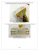
5.  To install the harness into the ECU plug, align the CANL and CANH pins into the 

receptacle of the plug and push in until it clicks as shown in figure 9: 


Figure 9: Pushing pin into ECU plug 

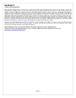
6.  Push the pin lock back into place until it is flush with the ECU plug as shown in figure 10: 


Figure 10: Ensure pin lock is relocked 


Summary of Contents for 30-3431

Page 1: ...net adapter is installed the Series 2 EMS will be able to send and receive data on the AEMnet Instructions for configuring the Series 2 EMS to output data are included in this manual Instructions on configuring the Series 2 EMS to receive data from other AEMnet enabled products are contained in the individual product manuals Upon completion of these instructions the Series 2 EMS will be configured...

Page 2: ... powered by AEMnet The red and black wires will need to be connected when using the Series 2 EMS with devices that are powered by AEMnet such as the Dyno Shaft see individual instructions for details The AEMnet connectors are shown below in figure 1 See table 1 for the AEMnet connection pinout Figure 1 AEMnet connectors wire entry view AEMnet Connector Series 2 EMS Connector Pin 1 White CAN1H Pin ...

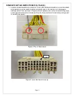
Page 3: ...lly pry white plastic retainer using both slots in the retainer so it disengages vertically about 1mm as shown in figures 2 and 3 please note some connectors may have a lock opposite to the wires in between the pins these can be removed simply using a pair of needle nose pliers Figure 2 Pry in these areas Figure 3 Lock that has to move up 1mm ...

Page 4: ...ying on the plastic tabs that secure the pin in the plastic connector while gently pulling on the wire at the same time as shown in figures 4 and 5 Figure 4 Pry this tab up with the screwdriver or paper clip to release pin Figure 5 While prying tab gently pull wire back ...

Page 5: ...R HARNESS 4 Table 2 below lists the corresponding CAN1L and CAN1H pin locations for each Series 2 EMS CAN1L Green wire CAN1H White wire EMS Adapter p n LOCATION LOCATION 30 6040 30 3431 A22 C2 30 6300 30 3434 75 13 Table 2 CAN1L and CAN1H pin locations Figures 7 and 8 below show the connectors for each Series 2 EMS Figure 7 Wire side view of pinout for 6040 EMS Figure 8 Wire side view of pinout fo...

Page 6: ...NL and CANH pins into the receptacle of the plug and push in until it clicks as shown in figure 9 Figure 9 Pushing pin into ECU plug 6 Push the pin lock back into place until it is flush with the ECU plug as shown in figure 10 Figure 10 Ensure pin lock is relocked ...

Page 7: ...ware and later To activate the AEMnet data stream open AEMTuner and go to Wizards Setup Wizard and select the AEMnet Data Stream See figure 11 below Figure 11 Selecting the AEMnet Datastream With the AEMnet enabled the Series 2 EMS broadcasts information as shown below in figure 12 Figure 12 AEMnet Data ...

Page 8: ...t and is non transferable All implied warranties shall be limited in duration to the said 12 month warranty period Improper use or installation accident abuse unauthorized repairs or alterations voids this warranty AEM disclaims any liability for consequential damages due to breach of any written or implied warranty on all products manufactured by AEM Warranty returns will only be accepted by AEM ...

Reviews: