background image

818 35 73-01/6

5

Important Safety Instructions

These warnings are provided in the interests of your safety. Ensure 
that you understand them all before installing or using this 
appliance. Your safety is of paramount importance. If you are unsure 
about any of the meanings of these warnings contact the Customer 
Care Department.

Prior to Installation

• Check the refrigerator for transport damage. Under no circumstances 

should a damaged appliance be installed! In the event of damage, 
please contact your retailer.

Installation

• This appliance is heavy. Care should be taken when moving it. 

• It is dangerous to alter the specifications or attempt to modify this 

product in any way.

• Ensure that the appliance does not stand on the electrical supply 

cable. If the supply cable is damaged, it must be replaced by a cable 
available from your local Service Force Centre.

• Make sure that the power plug is not squashed or damaged by the 

back of the appliance. A damaged power plug may overheat and 
cause a fire.

• If the power plug socket is loose, do not insert the power plug. There 

is a risk of electric shock or fire. 

• Any electrical work required to install this appliance should be carried 

out by a qualified electrician or competent person.

• Parts which heat up should not be exposed. Whenever possible, the 

back of the appliance should be close to a wall, but leaving the 
required distance for ventilation, as stated in the installation 
instructions.

• The appliance should be left for 2 hours after installation before it is 

turned on, in order to allow the refrigerant to settle.

Refrigerant

The refrigerant isobutane (R600a) is contained within the refrigerant 
circuit of the appliance, a natural gas with a high level of 
environmental compatibility, which is nevertheless flammable.

• During transportation and installation of the appliance, be certain 

that none of the components of the refrigerant circuit become 
damaged.

Summary of Contents for SANTO 72340 KA

Page 1: ...SANTO 72340 KA Electronic Refrigerator Operating Instructions 818 35 73 01 6 ...

Page 2: ...numbered instructions guide you step by step in the operation of the appliance 2 3 Supplementary information regarding operation and practical uses of the appliance appear after this symbol 2 Tips and notes concerning economical and environmentally sound use of the appliance are marked with the cloverleaf Explanations of the technical terminology used in the operating instructions can be found at ...

Page 3: ...al Connection 11 Installation of the carbon filter 12 Reversing the Door 13 Description of the Appliance 15 Control Panel 16 Buttons for Adjusting the Temperature 16 Temperature Display 17 ALARM OFF button 17 Prior to Initial Start Up 17 Initial Start Up 18 Temperature Adjustment 18 COOLMATIC 19 COOLMATIC button 19 Quick chill 19 Open Door Warning 20 Temperature warning 20 Switching the Appliance ...

Page 4: ...er Door 24 Bottle Holder 24 Proper Storage 25 Hints and Tips 26 Normal Operating Sounds 26 Food Storage 26 Energy Saving Advice 26 Defrosting 27 Maintenance and Cleaning 27 Internal Cleaning 27 External Cleaning 27 Changing the carbon filter 28 Replacing the Light Bulb 29 What to do if 30 Regulations Standards Guidelines 31 Technical Terminology 32 Guarantee Conditions 33 Service Spare Parts 35 ...

Page 5: ... Centre Make sure that the power plug is not squashed or damaged by the back of the appliance A damaged power plug may overheat and cause a fire If the power plug socket is loose do not insert the power plug There is a risk of electric shock or fire Any electrical work required to install this appliance should be carried out by a qualified electrician or competent person Parts which heat up should...

Page 6: ...ed storage times should be adhered to Refer to relevant instructions Maintenance and Cleaning Before cleaning always switch off the appliance and disconnect from the electrical supply When unplugging always pull the plug from the mains socket do not pull on the cable Damage to the cord may cause a short circuit fire and or electric shock Servicing This product should be serviced by an authorised e...

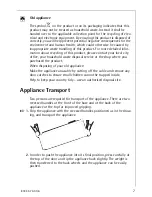
Page 7: ...disposal service or the shop where you purchased the product When disposing of your old appliance Make the appliance unusable by cutting off the cable and remove any door catches to ensure small children cannot be trapped inside Help to keep your country tidy use an authorised disposal site Appliance Transport Two persons are required for transport of the appliance There are two recessed handles a...

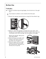
Page 8: ... the appliance with lukewarm water with a little bicarbonate of soda added 5 ml to 0 5 litre of water Do not use soap or detergent as the smell may linger Dry the appliance thoroughly Remove the transport fittings from the storage shelves 4 Slide the fittings securing the shelf forward to the thicker section on the edge of the storage shelf 5 Slide the storage shelf far enough forward so that it c...

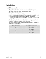
Page 9: ...other sources of heat only be installed at a location whose ambient temperature corresponds to the climate classification for which the appliance is designed The climate classification can be found on the rating plate which is located at the left on the inside of the appliance The following table shows which ambient temperature is correct for each climate classification Climate classification for ...

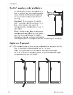
Page 10: ... cabinet above it must be maintained Please check whether after installing your appliance and especially after reversing the door the door seal fits tightly A badly fitting door seal may lead to heavy frosting and a higher power consumption see also Something not working Appliance Alignment 0 1 The appliance must be level please compensate for unevenness in the floor by turning the two adjustable ...

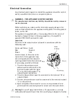
Page 11: ...oured in accordance with the following code Green and Yellow Earth Blue Neutral Brown Live As the colours of the wires in the mains lead of this appliance may not correspond with the coloured markings indentified in the terminals of your plug proceed as follows 1 The wire coloured green and yellow must be connected to the terminal marked with the letter E or by the earth symbol or coloured green a...

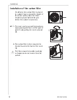
Page 12: ...lter The filter should be placed behind the grill before the cabinet is turned on 0 1 The cover can be opened by simultane ously pressing the lever on the right of grill 1 and pulling the cover outward 2 2 The carbon filter is then mounted in the slot found in the back of the cover 3 1 The filter should be handled carefully so fragments do not loosen from the surface ...

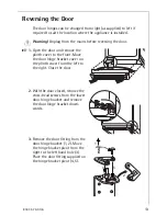
Page 13: ...he plinth cover to the front Move the door hinge bracket cover on the plinth cover from the left to the right Close the door 2 With the door closed remove the cross head screws from the lower door hinge bracket and remove the door hinge bracket down wards 3 Remove the door fitting from the door hinge bracket 1 2 Move the hinge bracket pivot from the right to the left hand hole 3 Place the door fit...

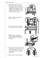
Page 14: ... front and place on one side 5 Move the upper hinge bracket pivot to the left 6 Carefully slide the door onto the top hinge bracket pivot and close 7 Place the lower door hinge bracket with the hinge bracket pivot in the lower left of the door and fasten 8 Move the door handle from the left to the right remove the hole cover pins 1 and cover the remaining holes with the hole cover pins attached 2 ...

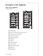
Page 15: ...pliance various models á Control panel à Butter and cheese compartment with lid â Door storage compartments ä Variable storage box ã Bottle compartment å Salad bin ç Shelves é Quick chill shelf è Filter housing ê Bottle and can holder ë Bottle rack í Rating plate ...

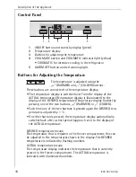
Page 16: ...s illuminated to the display of the DESIRED temperature Temperature display flashes by pressing one of the two buttons WARMER or COLDER Each time one of the two buttons is pressed again the DESIRED tem perature is adjusted by 1 C If neither button is pressed the temperature display automatically switches back after a short period approx 5 sec to the display of the ACTUAL temperature DESIRED temper...

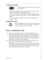
Page 17: ...Prior to Initial Start Up 1 Before connecting the appliance to the mains and putting it into operation for the first time leave the appliance to stand for 30 minutes if was transported upright After transport on its side the appliance must be left to stand for 2 hours before putting it into operation This is necessary to allow the refrigerant to flow back into the compressor Otherwise the compress...

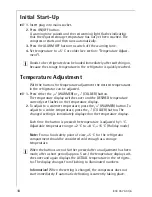
Page 18: ...y switches over and the DESIRED temperature currently set flashes on the temperature display 2 To adjust to a warmer temperature press the WARMER button To adjust to a colder temperature press the COLDER button The changed setting is immediately displayed on the temperature display Each time the button is pressed the temperature is adjusted by 1 C Adjustable temperature range 2 C to 8 C 15 C Holid...

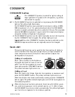
Page 19: ...e changed Quick chill The quick chill function can be used for the fast cooling of drinks in cans or bottles in the fast cool storage tray or of larger amounts of room temperature food The built in charcoal filter reduces the development of any smell Chilling of cans bottles Place cans or bottles in the holder on the quick chill shelf in front of the fan grille Turn the fan regulator to maxi mum a...

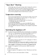
Page 20: ... off automatically when the ACTUAL temperature existing in the refrigerator drops below 12 C again Switching the Appliance off 0 1 To switch off push the ON OFF button This will result in a countdown from 3 to 1 taking place in the temperature display On reaching 1 the fridge will switch off The temperature display will go off 3 The appliance is only completely disconnected from the electricity su...

Page 21: ...button until the temperature display indicates H for holiday The temperature shown in the temperature display will change in steps of 1 C until it reaches 8 C After 8 C the value 15 C will appear in the display with the letter H The fridge is now operating in energy saving holiday mode 3 To switch the fridge back to normal operation press the COLDER button Important Do not store any goods in the r...

Page 22: ... up or down and removed 2 To insert at a different height use the same procedure in reverse Salad Bin The salad bin can be divided into sections by inserting the dividers 0 1 Insert the large divider in the mid dle or to the left side of the salad bin as required 2 If the large divider is inserted in the middle of the bin the right hand side can be further divided by inserting the small divider in...

Page 23: ...ilted upwards then slide the front sup port into the next level up Quick Chill Shelf The quick chill shelf can be placed in one of the upper grooves To maintain the best performance the shelf should be placed in the second groove from the top Bottle and Can Holder The side of the bottle and can hol der is moveable to enable a more flexible placement of cans and bottles in front of the grid To allo...

Page 24: ...ith holder from the cabinet 2 To loosen the holder from the shelf bend the hooks brackets that surround the backside of the shelf Variable Inner Door The door compartments can be pulled up and removed and inserted at other positions as needed Bottle Holder A bottle holder in the bottle compart ment is used to prevent individual bottles from falling over and can be slid sideways ...

Page 25: ... carry out the following test yourself 0 1 Place a cup of water in the centre of the said shelf with a thermometer inside 2 Leave the fridge door closed overnight and check the temperature first thing in the morning 3 At this point the temperature should read no more than 5 C if it does you need to adjust the temperature to a colder setting For further information on keeping food cool and safe a g...

Page 26: ... food uncovered Keep the time between buying chilled food and placing it in your refrigerator as short as possible Do not push food together too much try to allow air to circulate around each item 2 Energy Saving Advice Do not install the appliance close to sources of heat such as a cooker dishwasher or radiator Locate the appliance in a cool well ventilated room and make sure that the air opening...

Page 27: ...alcohol 2 Regularly check the door seals and wipe clean to ensure they are clean and free from debris External Cleaning 1 Warning Do not use abrasive products There are sharp edges on the underside of the product so care should be taken when cleaning 0 1 Clean the appliance with a cloth and lukewarm water Commercially available dish washing detergents may also be used Rinse and dry thor oughly 2 A...

Page 28: ...al Service Force Centre 0 1 The filter is placed behind the grill and can be reached by opening the cover The cover can be ope ned by simultaneously pressing the lever on the right of the grill 1 and pulling the cover outward 2 2 The carbon filter is then pulled out of its slot 3 3 The new carbon filter is placed in the existing slot 1 The filter should be handled care fully so fragments do not lo...

Page 29: ...n replacing the lamp only fit a lamp of suitable diameter that is at least 18 mm this will ensure a good seat on the rubber seal Where to purchase specialist retailer or AEG Service Force Centre 0 1 To switch the appliance off press the ON OFF button 2 Unplug the mains plug 3 To change the light bulb undo the cross head screw and remove the light bulb cover downwards 4 Change the defective light b...

Page 30: ...g display is flashing Door is opened for longer than 5 minutes Switch off the warning tone by pressing the ALARM OFF button Do not leave the door open for longer than necessary Red warning light flashing warning tone sounding Temperature warning Please look at Temperature warning section Temperature display shows a square or a letter There is a function fault Please inform your local Service Force...

Page 31: ...G accident prevention regulations for refrigeration appliances VBG 20 and the regulations of the German Society of Electrical Engineers VDE were observed in the manufacture of this appliance The refrigerant circuit has been checked for leaks This appliance is in accordance with the following EU guidelines 73 23 EWG dated 19 February 1973 low voltage guidelines 89 336 EWG dated 3 May 1989 including...

Page 32: ...o evaporate This heat is removed from the interior of the appliance as a result the interior is cooled The evaporator is therefore located inside the appliance or placed in foam immediately behind the inner wall and thus not visible Compressor The compressor looks like a small drum It is driven by a built in electric motor and is mounted on the base of the appliance at the rear The task of the com...

Page 33: ...aterials 5 Repairs carried out under guarantee do not extend the guarantee period for the appli ance Parts removed during guarantee repairs become the property of AEG 6 The purchaser s statutory rights are not affected by this guarantee European Guarantee If you should move to another country within Europe then your guarantee moves with you to your new home subject to the following qualifications ...

Page 34: ...34 818 35 73 01 6 ...

Page 35: ...of the fault 4 The model and serial number of the appliance found on the rating plate 5 The purchase date Please note that a valid purchase receipt or guarantee documentation is required for in guarantee service calls Customer Care For general enquiries concerning your AEG Electrolux appliance or for further information on AEG Electrolux products please contact our Customer Care Department by lett...

Page 36: ...55 million Electrolux Group products such as refrigerators cookers washing machines vacuum cleaners chain saws and lawn mowers are sold each year to a value of approx USD 14 billion in more than 150 countries around the world AEG Hausgeräte GmbH Postfach 1036 D 90327 Nürnberg http www aeg hausgeraete de Copyright by AEG 818 35 73 01 6 1205 Subject to change without notice ...

Reviews: