36
9. Insert the small transparent RJ11 plugs for the automatic
recognition of the battery units in the side in the
corresponding connection jacks.
10. As the last step, replace the front panels. The wires are
threaded carefully through the corresponding access slots
and are protected behind the front panels. Remember to
tighten the screws in the center to lock the panel into place.
6.2 Power connection
Compare the setting of the nominal input voltage for the UPS
with the nominal voltage used in your country. The default setting
for the UPS output voltage is 230 Vac. Alterations to 200 Vac,
208 Vac, 220 Vac, 230 Vac or 240 Vac can be made on the
operating panel.
To guarantee that the UPS and its accessories all operate
correctly, it is necessary to equip the AC power line with a
corresponding back-up fuse. All the models in the PROTECT D
series are connected using the power cord supplied with the
device to a conventional power outlet. Make sure that the fuse is
adequately dimensioned to support your sub-distribution. The
PROTECT D. 3000 in particular requires its own fuse with 16A.
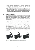
Any unintentional release/pulling out of the power cord can be
avoided by using the clips that come with the device (also see
Fig. 17). Do not plug the power cord connector into the power
outlet yet.
Fig. 17: Plugging in and securing the input power cord
Summary of Contents for protect d. 1000
Page 2: ...2 ...
Page 21: ...21 EN 3 3 CE certificate ...
Page 73: ...73 EN 12 3 Notes ...
Page 74: ...74 ...
Page 75: ...75 EN ...

