background image

INSTALLATION

WARNING!

Refer to "Safety information"
chapter.

WARNING!

The following instructions about
installation, connection and main-
tenance must be carried out by
qualified personnel in compliance
with standards and local regula-
tions in force.

IMPORTANT SAFETY
REQUIREMENTS

This hob must be installed in accordance
with the Gas Safety (Installation and Use)
Regulations (Current Edition) and the IEE
Wiring Regulations (Current Edition).
For appliances installed in the Republic of
Ireland please refer to NSAI- Domestic
Gas Installation I.S. 813 Current Editions
and the ETCI Rules for Electrical Installa-
tions.

Provision for ventilation

Detailed recommendations are contained
in the following British Standards Codes
Of Practice: B.S. 6172/ B.S. 5440, Par. 2
and B.S. 6891 Current Editions.
The hob should not be installed in a bed
sitting room with a volume of less than 20
m³. If it is installed in a room of volume
less than 5 m³ an air vent of effective area
of 100 cm² is required. If it is installed in a
room of volume between 5 m³ and 10 m³
an air vent of effective area of 50 cm² is
required, while if the volume exceeds 11
m³ no air vent is required.
However, if the room has a door which
opens directly to the outside no air vent is
required even if the volume is between 5
m³ and 11 m³.
If there are other fuel burning appliances
in the same room, B.S. 5440 Part 2 Cur-
rent Edition, should be consulted to de-
termine the requisite air vent require-
ments.
For appliances installed in the Republic of
Ireland please refer to the NSAI- Domes-
tic Gas Installation I.S. 813 Current Edi-
tions Table Four.

Location

The hob may be located in a kitchen, a
kitchen/diner or bed sitting room (with a
volume greater than 20 m³), but not in a
bathroom or shower room.
The minimum distance combustible mate-
rial can be fitted above the hob in line
with the edges of the hob is 400 mm. If it
is fitted below 400 mm a space of 50 mm
must be allowed from the edges of the
hob.
For appliances installed in the Republic of
Ireland please refer to NSAI- Domestic
Gas Installation I.S 813 Current Edition
Section 7- Permitted Locations of Appli-
ance.

GAS CONNECTION

WARNING!

Any gas installation must be car-
ried out by a GAS SAFE REGIS-
TER installer.

Make sure that, once the hob is installed,
it is easily accessible for the engineer in
the event of a breakdown.
The manufacturer will not accept liability,
should the above instructions or any of
the other safety instructions incorporated
in this instruction booklet be ignored.
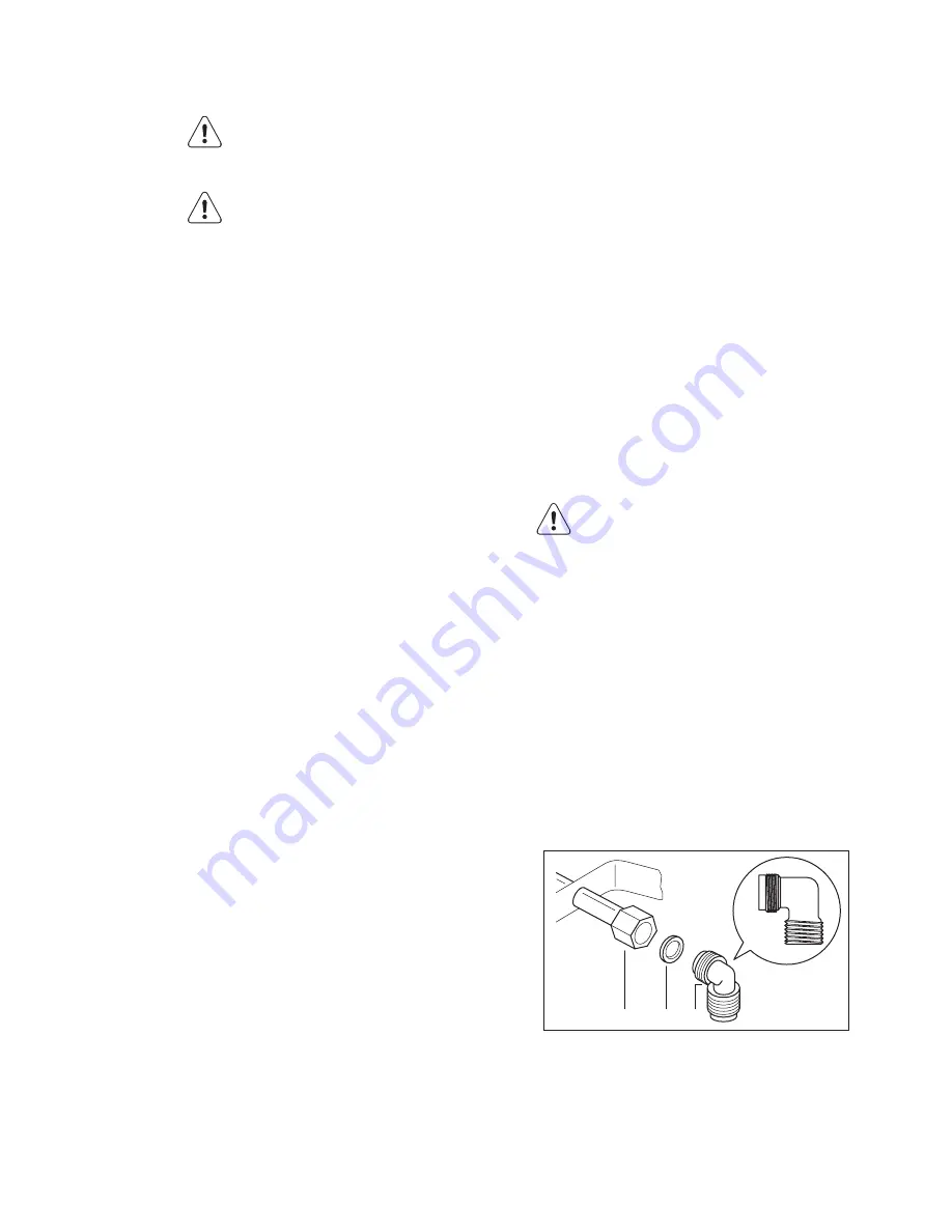
On the end of the shaft, which includes
the G 1/2" threaded elbow, adjustment is
fixed so that the washer is fitted between
the components as shown in the diagram.
Screw the parts together without using
excessive force.

A

B C

A)

End of shaft with nut

B)

Washer

C)

Elbow

Connection to the gas supply should be
with either rigid or semi-rigid pipe, i.e.
steel or copper.

14 www.aeg.com

Summary of Contents for HG795540XB

Page 1: ...HG795540XB EN HOB USER MANUAL ...

Page 2: ...s to recycle it Help protect the environment and human health and to recycle waste of electrical and electronic appliances Do not dispose appliances marked with the symbol with the household waste Return the product to your local recycling facility or contact your municipal office VISIT OUR WEBSITE FOR Products Brochures User manuals Trouble shooter Service information www aeg com LEGEND Warning I...

Page 3: ... find everything you need to keep all your AEG appliances looking spotless and working perfectly Along with a wide range of accessories designed and built to the high quality standards you would expect from specialist cookware to cutlery baskets from bottle holders to delicate laundry bags Visit the webshop at www aeg com shop CUSTOMER CARE AND SERVICE We recommend the use of original spare parts ...

Page 4: ...e from steam and moisture Do not install the appliance adjacent to a door or under a window This pre vents hot cookware to fall from the ap pliance when the door or the window is opened If the appliance is installed above draw ers make sure that the space between the bottom of the appliance and the upper drawer is sufficient for air circula tion The bottom of the appliance can get hot We recommend...

Page 5: ... a lower temper ature than oil used for the first time Do not put flammable products or items that are wet with flammable products in near or on the appliance Do not try to extinguish a fire with wa ter Disconnect the appliance and cover the flame with a lid or a fire blanket WARNING Risk of damage to the appliance Do not keep hot cookware on the con trol panel Do not let cookware to boil dry Be c...

Page 6: ...e cleaning pads solvents or metal ob jects DISPOSAL WARNING Risk of injury or suffocation Contact your municipal authority for in formation on how to discard the appli ance correctly Disconnect the appliance from the mains supply Cut off the mains cable and discard it Flat the external gas pipes 6 www aeg com ...

Page 7: ... 4 5 6 1 Triple Crown burner 2 Semi rapid burner 3 Semi rapid burner 4 Semi rapid burner 5 Auxiliary burner 6 Control knobs CONTROL KNOBS Symbol Description no gas supply off position ignition position maximum gas supply minimum gas supply ENGLISH 7 ...

Page 8: ...l knob A B C A Burner cap and crown B Thermocouple C Ignition candle C D B A A Burner cap B Burner crown C Ignition candle D Thermocouple WARNING Do not keep the control knob pushed for more than 15 seconds If the burner does not light after 15 seconds release the control knob turn it into off position and try to light the burner again after minimum 1 minute In the absence of electricity you can i...

Page 9: ...WARNING Always turn the flame down or switch it off before you remove the pans from the burner ENGLISH 9 ...

Page 10: ...tes on gas burners WARNING Do not put the same pan on two burners WARNING Make sure pot handles do not protrude over the front edge of the cooktop and that pots are centrally positioned on the rings in order to achieve maximum sta bility and to obtain lower gas con sumption Do not place unstable or deformed pots on the rings to prevent from spill and in jury WARNING Liquids spilt during cooking ca...

Page 11: ... the hob top from damage After cleaning dry the appliance with a soft cloth Removing the dirt 1 Remove immediately melting plastic plastic foil and food con taining sugar Stop the appliance and let it cool down before you clean limescale rings water rings fat stains shiny metallic discolorations Use a spe cial cleaner for glass or stainless steel 2 Clean the appliance with a damp cloth and some de...

Page 12: ...or is not blocked and the burner crown is clear of food particles If there is a fault first try to find a solution to the problem yourself If you cannot find a solution to the problem yourself speak your dealer or the local Service Force Centre If you operated the appliance in correctly or the installation was not carried out by a registered en gineer the visit from the customer service technician...

Page 13: ...O SER NO DATA MODEL MODEL MOD PROD NO SER NO 03 IT MADE IN ITALY TYPE 230V 50Hz IP20 0049 1 2 3 1 Stick it on Guarantee Card and send this part 2 Stick it on Guarantee Card and keep this part 3 Stick it on instruction booklet ENGLISH 13 ...

Page 14: ...ame room B S 5440 Part 2 Cur rent Edition should be consulted to de termine the requisite air vent require ments For appliances installed in the Republic of Ireland please refer to the NSAI Domes tic Gas Installation I S 813 Current Edi tions Table Four Location The hob may be located in a kitchen a kitchen diner or bed sitting room with a volume greater than 20 m but not in a bathroom or shower r...

Page 15: ...ply pipe with the one for the new type of gas supply You can find this plate in the package supplied with the appliance If the supply gas pressure is changeable or different from the necessary pressure you must fit an applicable pressure adjust er on the gas supply pipe ADJUSTMENT OF MINIMUM LEVEL To adjust the minimum level of the burn ers 1 Light the burner 2 Turn the knob on the minimum posi ti...

Page 16: ...upply Before activating the appliance make sure the electrical supply voltage is the same as that indicated on the rating plate The rating plate is located on the bottom of the appliance The appliance is supplied with a 3 core flexible supply cord with a 3 amp plug If it is necessary to change the fuse use a 3 amp ASTA approved BS 1362 fuse 1 2 3 4 5 1 Green and Yellow 2 3 amp fuse 3 Brown 4 Cord ...

Page 17: ...490 mm 2 0 2 0 A A supplied brackets POSSIBILITIES FOR INSERTION Kitchen unit with door The panel installed below the hob must be easy to remove and let an easy access in case a technical assistance intervention is necessary min 20 mm max 150 mm 40 mm 60 mm B A A Removable panel B Space for connections Kitchen unit with oven The hob recess dimensions must obey the indication and the kitchen unit m...

Page 18: ...p cartridge fuse Category II2H3 Gas connection R 1 2 Gas supply G20 2H 20 mbar Appliance class 3 By pass diameters Burner Ø By pass in 1 100 mm Auxiliary 28 Semi rapid 32 Triple Crown 56 Gas burners BURN ER NOR MAL POWER RE DUCED POWER NORMAL POWER NATURAL GAS G20 2H 20 mbar LPG Butane Propane G30 G31 3 28 30 37 mbar kW kW inj 1 100 mm m h inj 1 100 mm G30 28 30 mbar G31 37 mbar g h g h Auxili ary...

Page 19: ...ENGLISH 19 ...

Page 20: ...www aeg com shop 397249302 A 042012 ...

Reviews: