AEG B 99852G User Manual Download Page 12

12

700 mm

400 mm

400 mm

100 mm

50 mm

50 mm

55 mm

700 mm

400 mm

100 mm

400 mm

50 mm

50 mm

55 mm

CLEARANCES REQUIRED WHEN FITTING THE GAS HOB

WITHOUT A COOKER HOOD ABOVE

CLEARANCES REQUIRED WHEN FITTING THE GAS HOB

WITH A COOKER HOOD ABOVE

FO 2028*

FO 2027*

Instructions for the Installer

Important safety requirements

This hob must be installed in accordance with the Gas Safety (Installation and Use) Regulations
(Current Edition) and the IEE Wiring Regulations (Current Edition). For appliances installed in the
Republic of Ireland please refer to NSAI- Domestic Gas Installation I.S. 813 Current Editions and the
ETCI Rules for Electrical Installations. Detailed recommendations are contained in the following
British Standards Codes Of Practice: B.S. 6172/ B.S. 5440, Par. 2 and B.S. 6891 Current Editions.

Provision for ventilation

The hob should not be installed in a bed sitting room with a volume of less than 20 m

3

. If it is installed

in a room of volume less than 5 m

3

 an air vent of effective area of 110 cm

2

 is required. If it is installed

in a room of volume between 5 m

3

 and 10 m

3

 an air vent of effective area of 50 cm

2

 is required, while

if the volume exceeds 11 m

3

 no air vent is required. However, if the room has a door which opens

directly to the outside no air vent is required even if the volume is between 5 m

and 11 m

3

. If there are

other fuel burning appliances in the same room, B.S. 5440 Part 2 Current Edition, should be
consulted to determine the requisite air vent requirements. For appliances installed in the Republic of
Ireland please refer to the NSAI- Domestic Gas Installation I.S. 813 Current Editions Table Four.

Location

The hob may be located in a kitchen, a kitchen/diner or bed sitting room, but not in a bathroom,
shower room or garage. Before making the cut out in the worktop ensure that there is a minimum
distance of 55 mm between the rear edge of the hob and the wall. A minimum distance of 100 mm
must be left between the side edges of the hob and any adjacent cabinets or walls. The minimum
distance combustible material can be fitted above the hob in line with the edges of the hob is 400 mm
If it is fitted below 400 mm a space of 50 mm must be allowed from the edges of the hob. The
minimum distance combustible material can be fitted directly above the hob is 700 mm. For
appliances installed in the Republic of Ireland please refer to NSAI- Domestic Gas Installation I.S 813
Current Edition Section 7- Permitted Locations of Appliance.

Summary of Contents for B 99852G

Page 1: ...B 99852G User Manual Hob ...

Page 2: ...houldbekeptawayuntilithascooled z Childrencanalsoinjurethemselvesbypullingpansorpotsoffthehob z Thisapplianceisnotintendedforusebychildrenorotherpersonswhosephysical sensory or mental capabilities or lack of experience and knowledge prevents them from using the appliance safely without supervision or instruction by a responsible persontoensurethattheycanusetheappliancesafely During Use z This hob ...

Page 3: ...seofthepackagingwithdueregardtosafetyandthe environment z Whendisposingofanoldappliance makeitunusable bycuttingoffthecable z Thesymbol ontheproductoronitspackagingindicatesthatthisproductmay notbetreatedashouseholdwaste Insteaditshallbehandedovertotheapplicable collectionpointfortherecyclingofelectricalandelectronicequipment Byensuring this product is disposed of correctly you will help prevent p...

Page 4: ...tsandTips EnvironmentalInformation Contents Instructions for the User Important Safety Information 2 Description of the Hob 5 Operation 6 Maintenance and Cleaning 8 Something Not Working 10 Service and Spare Parts 11 Customer Care 24 Guarantee Conditions 25 European Guarantee 26 Instructions for the Installer Important safety requirements 12 Installation 13 Building In 14 Electrical connections 17...

Page 5: ... competent person and in accordance with existing rules and regulations Therelevantinstructionsaretobefoundinthesecondsectionofthismanual Please ensurethat oncethehobisinstalled itiseasilyaccessiblefortheengineerinthe eventofabreakdown WHEN THE HOB IS FIRST INSTALLED Oncethehobhasbeeninstalled itisimportanttoremoveanyprotectivematerials which wereputoninthefactory 1 2 5 2 2 4 3 ...

Page 6: ... control knob Whenswitchingonthemains afterinstallationora powercut itisquitenormalforthesparkgenerator tobeactivatedautomatically Operation As soon as a liquid starts boiling turn down the flamesothatitwillbarelykeeptheliquidsimmering If you use a saucepan which is smaller than the recommendedsize theflamewillspreadbeyond the bottom of the vessel causing the handle to overheat Take care when fryi...

Page 7: ... of wok or pan When fitting the wok stand ensure the recessesdintheframefitsecurelyontothebars of the pan supports as shown in figure 2 Burner minimum maximum diameter diameter Large ultra rapid 180 mm 260 mm Medium semi rapid 120 mm 220 mm Small Auxiliary 80 mm 160 mm To ensure maximum burner efficiency you should only use pots and pans with a flat bottomfittingthesizeoftheburnerused seetable ...

Page 8: ...edpadsunsuitablefornon stick saucepans steelwoolpads bath sink stain removers Should the hob top become heavily soiled the following product s are recommended for stainless steel hobs use a proprietarystainlesssteelcleaner for other hobs use Hob Brite or Bar Keepers Friend If scratches or cracks are noticed disconnect the appliance from the electrical supply and call your nearest Service Force Cen...

Page 9: ...susingapastecleaner The Burners The burner caps and crowns can be removed for cleaning Washtheburnercapsandcrownsusinghotsoapywater andremovemarkswithamild paste cleaner A well moistened soap impregnated steel wool pad can be used with caution ifthemarksareparticularlydifficulttoremove Aftercleaning besuretowipedry withasoftcloth Ignition electrode Theelectricignitionisobtainedthroughaceramic elec...

Page 10: ...rnercapandcrownhavebeen replacedcorrectly e g aftercleaning Check the main jet is not blocked and the burnercrownisclearoffoodparticles Checktheburnercapandcrownhavebeen replacedcorrectly e g aftercleaning If after all these checks your hob still does not operate correctly contact your local Service Force Centre Please note that it will be necessary to provide proof of purchase for any in guarante...

Page 11: ...s 50 7 MJ m3 TYPEOFGAS LPG GAS 28 30 37 mbar VALUE 49 92 MJ Kg Burner Dia Tap By pass 1 100mm Auxiliary 28 Semi rapid 32 Ultra rapid 56 Aerationadjustmentnone Supply Connections Gas RC 1 2 inch 1 2 inch male Rear right hand corner Electric 230 V 50 Hz supply 3 core flexible cable with non rewireable plug fitted with a 3 ampcartridgefuse Heat Input Ultra rapid Burner 3 8 kW Natural Gas Triple crown...

Page 12: ...nd10m3 anairventofeffectiveareaof50cm2 isrequired while ifthevolumeexceeds11m3 noairventisrequired However iftheroomhasadoorwhichopens directlytotheoutsidenoairventisrequiredevenifthevolumeisbetween5m3 and11m3 Ifthereare otherfuelburningappliancesinthesameroom B S 5440Part2CurrentEdition shouldbe consultedtodeterminetherequisiteairventrequirements ForappliancesinstalledintheRepublicof Irelandpleas...

Page 13: ... the partstogetherwithoutusingexcessiveforce Gas Connection Connection to the gas supply should be with either rigid or semi rigid pipe i e steel or copper TheconnectionshouldbesuitableforconnectingtoRC1 2 1 2BSPmalethread When the final connection has been made it is essential that a thorough leak test is carriedoutonthehobandinstallation Ensurethatthemainconnectionpipedoesnotexertanystrainontheh...

Page 14: ... to be installed above a cupboard or drawer it will be necessary to fit a heat resistantboardbelowthebaseofthehobontheundersideoftheworksurface It is also recommended to carry out the electrical connection to the hob as shown in diagrams 1 and 2 See next page 880 510 InstructionsfortheInstaller 830 4 8 0 30 150 min FO 2349 ...

Page 15: ... inordertoavoid anycontactwiththebottomofthehobwhich can be heated when it is operated The recommendedsolutionisshownindiagram 3 Thepanelfittedunderthehob a should be easily removable to allow easy access iftechnicalassistanceisneeded Thespace behind the kitchen unit b can be used forconnections 30 20 min 60 a b FO 1013 3 Dimensions are given in mm InstructionsfortheInstaller ...

Page 16: ...thehobseepingintothecabinetbelow 1 Removethepansupports theburnerscapsandcrownsandturnthehobupsidedown taking care the ignition electrodes are not damaged in this operation 2 Placethesealinggasketallaroundtheglasstopedgeasshownindiagram4 3 Fit the hob in the cut out and push it down until the glass top and the working top make contact asshownindiagram5 a Sealing FO 2320 FO 2321 a 4 5 Instructionsf...

Page 17: ...sed Should the plug need to be replaced for any reason the wires in the mains lead are colouredinaccordancewiththefollowingcode GreenandYellow Earth Blue Neutral Brown Live 1 Connect the green and yellow earth wire to the terminal in the plug which is marked with the letter E or the earth symbol or colouredgreenandyellow 2 Connecttheblue neutral wiretotheterminal intheplugwhichismarkedwiththelette...

Page 18: ...hob supply cord does not come into contact with surfaces with temperatures higher than 50 deg C Wiring diagram 1 IGNITOR SWITCHES 2 IGNITOR UNIT 3 LED POWER INDICATORS Replacement of the cable Theconnectionofthevoltagecabletotheappliance sterminalblockisoftype Y This meansthatitsreplacementrequiresthespecificequipmentofatechnician Inthiscase onlycabletypesH05RR F H05V2V2 F T90 orH05BB Fmustbeused ...

Page 19: ...uld now be satisfactory Carry out D Resistance to Earth check Inlet wiring faulty Rectify any fault Isolateapplianceand carry out B Insulation check Rectify any fault includingreplacing fuses as necessary NO YES SOCKET face view PLUG with cover removed Earth Wire Green Yellow Neutral Wire Blue FUSE E N L Brown Blue Green Yellow Green Yellow Brown Blue NO YES InstructionsfortheInstaller ...

Page 20: ...e TestleadsfromLtoNinapplianceterminalblock Ifmeterreads 0 thenthereisa shortcircuit b meter set on Ω Ohm x 100 scale RepeattestwithleadsfromLtoE Ifmeterreadslessthan infinity thereisafault NOTE Shoulditbefoundthatthefusehasfailedbutnofaultisindicated adetailedcontinuity check i e by disconnecting and checking each component is required to trace the faulty component Itispossiblethatafaultcouldoccu...

Page 21: ...simmer adjusted Light burner manually Check continuity from N on the mains connector block and O on theignitorunit Check continuity from L on the mains connector block and the taps ignition switches Check continuity from ignition switches connector to ignitor unit Check continuity from the tip of each electrode to the terminals 1 to 4 on the ignitor unit Check for breaks in the insulation of the H...

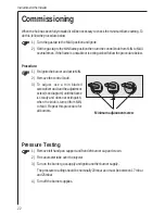
Page 22: ...N 2 Removethecontrolknob 3 To adjust use a thin bladed screwdriverandturntheadjustment screw seediagram untiltheflame is steady and does not extinguish when the knob is turned from MIN to MAX Repeat this procedure for allburners Pressure Testing 1 Removelefthandpansupportandfrontleftburnercapandcrown 2 Fitmanometertubeovertheinjector 3 Turnontheburnergassupplyandigniteanotherburnersupply The press...

Page 23: ...tedand thegasrateisadjustedtosuit Method 1 Ensurethatthegastapsareinthe OFF position 2 Isolatethehobfromtheelectricitysupply 3 Remove all pan supports burner caps rings crowns and control knobs 4 Withtheaidofa7mmboxspannertheburnerinjectorscanthenbeunscrewedand replacedbytheappropriateLPGinjectors To adjust the gas rate Withtheaidofathinbladedscrewdrivercompletelytightendownthebypassadjustment scr...

Page 24: ...tyourlocalServiceForceCentrebytelephoning 08705929929 YourtelephonecallwillbeautomaticallyroutedtotheServiceForceCentrecoveringyour postcode area For the address of your local Service Force Centre and further informa tionaboutServiceForce pleasevisitthewebsiteat www serviceforce co uk calls to this number may be recorded for training purposes Customer Care ForgeneralenquiriesconcerningyourElectrol...

Page 25: ...kenapartortamperedwith by any person not authorised by us Electrolux Service Force Centre must undertake all service work under this guarantee AnyapplianceordefectivepartreplacedshallbecometheCompany sproperty Thisguaranteeisinadditiontoyourstatutoryandotherlegalrights Exclusions This guarantee does not cover Damageorcallsresultingfromtransportation improperuseorneg lect thereplacementof anylightb...

Page 26: ...ntissuedbythesellerof theappliance Theapplianceguaranteeisforthesameperiodandtothesameextentforlabourand partsasexistsinyournewcountryofresidenceforthisparticularmodelorrangeof appliances Theapplianceguaranteeispersonaltotheoriginalpurchaseroftheapplianceand cannotbetransferredtoanotheruser TheapplianceisinstalledandusedinaccordancewithinstructionsissuedbyElec trolux and is only used within the ho...

Page 27: ...27 ...

Page 28: ...35686 0204 AM 02 07 Grafiche MDM Forlì www aeg electrolux co uk AEGHaugeräteGmbH Postfach1036 D 90327 Nürnberg http www aeg hausgeraete de Copyright byAEG ...

Reviews: