background image

4

• The national Standard on fuel-burning systems specifies a maxi-

mum depression of 0.04 mbar in such rooms.

• The air outlet must not be connected to chimney flues or combus-

tion gas ducts. The air outlet must under no circumstances be
connected to ventilation ducts for rooms in which fuel-burning
appliances are installed.

• The air outlet installation must comply with the regulations laid down

by the relevant authorities.

• When the unit is used in its extractor version, a sufficiently large

ventilation hole must be provided, with dimensions that are approxi-
mately the same as the outlet hole.

• National and regional building regulations impose a number of

restrictions on using hoods and fuel-burning appliances connected
to a chimney, such as coal or oil room-heaters and gas fires, in the
same room.

• Hoods can only be used safely with appliances connected to a

chimney if the room and/or flat (air/environment combination) is
ventilated from outside using a suitable ventilation hole approxi-
mately 500-600 cm

 large to avoid the possibility of a depression

being created during operation of the hood.

• If you have any doubts, contact the relevant controlling authority or

building inspector’s office.

• Since the rule for rooms with fuel burning appliances is “outlet hole

of the same size as the ventilation hole”, a hole of 500-600 cm

2

,

which is to say a larger hole, could reduce the performance of the
extractor hood.

• If the hood is used in its filtering function, it will operate simply and

safely in the above conditions without the need for any of the
aforementioned measures.

• When the hood is used in its extractor function, the following rules

must be followed to obtain optimal operation:
— short and straight outlet hose
— keep bends in outlet hose to a minimum
— never install the hoses with an acute angle, they must always

follow a gentle curve.

— keep the hose as large as possible (preferably the same diam-

eter as the outlet hole).

• Failure to observe these basic instructions will drastically reduce the

performance and increase the noise levels of the extractor hood.

Summary of Contents for 8160 D

Page 1: ...8160 D 8190 D 8260 D 8290 D 8360 D 8390 D 8361 D 8391 D Cooker Hood Campana extractora Exaustor Operating and Installation Instructions Instrucciones de montaje y manejo Manual de Instruções ...

Page 2: ...Panel 8160 D 8190 D 8260 D 8290 D 6 Control Panel 8360 D 8390 D 8361 D 8391 D 7 Maintenance and care 8 Cleaning the hood 8 Metal grease filter 8 Removing the metal grease filter 8 Charcoal filter 9 Changing the light bulb 10 What to do if 11 Special accessories 12 Technical assistance service 12 Technical Details 13 Mounting accessories included 12 Electrical connection 65 Wall unit mounting 66 ...

Page 3: ...utomatic circuit breaker It is very important to clean the hood and replace the filter at the recommended intervals Failure to do so could cause grease deposits to build up resulting in a fire hazard The appliance is not intended for use by young children or infirm persons without supervision Young children should be supervised to ensure that they do not play with the appliance WARNING Ensure that...

Page 4: ...lated from outside using a suitable ventilation hole approxi mately 500 600 cm2 large to avoid the possibility of a depression being created during operation of the hood If you have any doubts contact the relevant controlling authority or building inspector s office Since the rule for rooms with fuel burning appliances is outlet hole of the same size as the ventilation hole a hole of 500 600 cm2 w...

Page 5: ... Should there already be a pipe of diameter 125 mm that ducts to the outside through the walls or roof it is possible to use the 150 125 mm reduction flange provided In this case the hood will be slightly noisier Filter Version The air is filtered through an charcoal filter and returned to the kitchen through the top grill of the outlet pipe You will need an original AEG charcoal filter for the fi...

Page 6: ...the odours have disappeared The control switches are located on the unit s front panel 8160 D 8190 D the light switch switches the hood lamp on and off the motor switch switches the motor on and off enabling you to select one of the three different speeds Light switch Motor switch 8260 D 8290 D the light switch switches the hood lamp on and off the motor switch switches the motor off Speed 1 Speed...

Page 7: ...Mains switch OFF B Start and choice of motor speed 1 2 3 1 2 C Indicates speed 1 LED D Indicates speed 2 LED E Indicates speed 3 LED F Indicates Intensive speed LED G Intensive speed on off The Intensive speed runs for 5 minutes If the hood is on when the Intensive speed is activated the hood reverts to previous speed after 5 minutes If the hood is off when the Intensive speed is activated the hoo...

Page 8: ...rm during cooking and it must always be used either in the external extraction or internal recycling function Attention the metal grease filters must be removed and washed either by hand or in the dishwasher every four weeks Removing the metal grease filter First push the metal grease filter stop backwards then extract the filter pulling downwards Fig 3 Hand washing Soak grease filters for about o...

Page 9: ...o that no food parts gets stuck on the filter and later causes bad odours To reactivate the carbon the filter should be dried in an oven for 10 minutes with a temperature of maximum 100º C After approximately three years of use the carbon filter should be replaced with a new as the odour reduction capacity will be reduced Mounting Fig 4 Put the charcoal filter frame in place and fix it with 5 scre...

Page 10: ...ve the above safety recommendations Changing the light bulb Disconnect the cooker hood from the main supply 8160 D 8190 D Remove the lamp cover Fig 5 Replace the old bulb with a new one of the same type Remount the lamp cover 8260 D 8290 D 8360 D 8390 D 8361 D 8391 D Press 1 the lamp cover 2 and open it Fig 6 Replace the old bulb with a new one of the same type 3 Close the lamp cover If the light ...

Page 11: ...check that the ducting and outlets are not blocked The cooker hood has The safety cut out device has been switched off during operation tripped Turn off the hob and then wait for the device to reset If the hood has been installed below the heights indicated in the installation instructions the motor will cut out frequently which will damage the hood If after all these checks the problem persists c...

Page 12: ...pare parts contact your local AEG Service Force Centre by telephoning 08705 929 929 Your telephone call will be automatically routed to the Service Centre covering your post code area For the address of your local Service Force Centre and further information about Service Force please visit the website at www serviceforce co uk Please ensure that you have read the section What to do if as the engi...

Page 13: ...h Depth absorbedpower power of the cableconnection 8160 D 80 135 59 8 47 170 W 1 x 155 W 1 x 11 W PL 150 cm 220 240 V 8190 D 82 137 89 8 48 170 W 1 x 155 W 1 x 11 W 150 cm 220 240 V 8260 D 80 135 59 8 47 200 W 1 x 155 W 2 x 20 W G4 150 cm 220 240 V 8290 D 82 137 89 8 48 200 W 1 x 155 W 2 x 20 W G4 150 cm 220 240 V 8360 D 80 135 59 8 47 175 W 1 x 130 W 2 x 20 W G4 150 cm 220 240 V 8390 D 82 137 89 ...

Page 14: ...Fixed connection of the appliance must only be carried out by an authorised electrician Electrical connection for UK only Safety warnings for the electrician Connect the hood to the mains supply via a double pole switch which has 3 mm minimum separation between the contacts The switch must be accessible at all times The following is valid in the United Kingdom only the wire which is coloured green...

Page 15: ...th the screws 9 Mount the chimney support 10 with the wall plugs 9 and the screws 11 Be careful that it is centered over the hood and horizontally aligned Extractor version S Connect a tube between the hood air outlet and the wall or roof exhaust channel Fix it with the tube clamps supplied Filter version K Mount the deflector with the two screws supplied 2 9x13 mm 13 Make the electrical connectio...

Page 16: ...16 Electric hob 500 mm Gas hob 650 mm Fig 7 ...

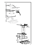
Page 17: ...17 240 22 599 899 370 270 350 Exhaust tube Power outlet Electric hob 500 mm Gas hob 650 mm Wall bracket Electric hob 500 mm Gas hob 650 mm 8160 D 8260 D 8360 D 8361 D 8190 D 8290 D 8390 D 8391 D ...

Page 18: ......

Page 19: ......

Page 20: ...rld s No 1 choice The Electrolux Group is the world s largest producer of powered appliances for kitchen cleaning and outdoor use More than 55 million Electrolux Group products such as refrigerators cookers washing machines vacuum cleaners chain saws and lawn mowers are sold each year to a value of approx USD 14 billion in more than 150 countries around the world ...

Reviews: