background image

51

The appliance is designed to be connected to 230 V monophase electricity supply.
The connection must be carried out in compliance with the laws and regulations in force.

Before the appliance is connected:

1) check that the main fuse and the domestic installation can support the load (see the rating label);
2) check that the power supply is properly earthed in compliance with the current rules;
3) check the socket or the double pole switch used for the electrical connection can be easily reached

with the appliance built in the forniture unit.

The appliance is supplied with a connection cable. This has to be provided with a proper plug, able
to support the load marked on the identification plate.  To connect the plug to the cable, follow the
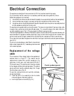
recommendation given in Fig. 5. The plug has to be fitted in a proper socket.
If connecting the appliance directly to the electric system, it is necessary that you install a double pole
switch between the appliance and the electricity supply, with a minimum gap of 3 mm. between the
switch contacts and of a type suitable for the required load in compliance with the current rules.
The connection cable has to be placed in order that, in each part, it cannot reach a temperature higher
than  90°C.
The brown coloured phase cable (fitted in the terminal
block contact marked with "L") must always be connected
to the network phase.

Replacement of the voltage
cable

The connection of the voltage cable to the appliance's
terminal block is of type "Y". This means that its
replacement requires the specific equipment of a
technician. In this case, only cable type H05V2V2-F
T90 must be used. The cable section must be suitable
to the voltage and the working temperature. The yellow/
green earth wire must be approximately 2 cm. longer
than the phase wires (Fig. 5).
To open the terminal block and reach the terminals,
proceed as follows:

insert the point of a screwdriver into the visible
protrunding part of the terminal block;
exert a light pressure and lift (Fig. 5-b).

Electrical Connection

Fig. 5

Fig.5-b

FO 0257

Neutral

Earth (yellow/green)

Summary of Contents for 79850 G

Page 1: ...79850 G Piano di cottura Plano de cozedura Gas hob Istruzioni per l uso Instru es de utiliza o Operating Instructions IT PT HU...

Page 2: ...pthemfarenoughfromtheheatedpartsofthisappliance Iftheapplianceisoutoforder disconnectitfromtheelectricsupply Child Safety This appliance has been designed to be operated by adults and children under s...

Page 3: ...s any responsability should all the safety measures not be carried out Service Undernocircumstancesshouldyouattempttorepairtheapplianceyourself Repairscarriedout by unexperienced persons may cause inj...

Page 4: ...ation to different types of gas 52 Building In 53 Possibilities for insertion 54 Thefollowingsymbolswillbefoundinthetexttoguideyou throughouttheInstructions SafetyInstructions Stepbystepinstructionsfo...

Page 5: ...D to beheatedandthesafetydevicetobeswitchedoff otherwise thegassupplywouldbeinterrupted Then checktheflameis regularandadjustitasrequired Ifyoucannotlighttheflameevenafterseveralattempts checkthe cap...

Page 6: ...ork Washtheenamelledcomponentswithwarmsoapywater Never use abrasive cleaners Frequently wash the caps and the crowns with hot soapy water carefully taking away any built up of food The pan supports ar...

Page 7: ...as supply pipe and the pressure adjuster if fitted To ensure the good operation of the hob and its safety features it is necessary that the taps are periodically lubricated The periodic lubrication of...

Page 8: ...finflammablematerials e g curtains tea towels etc This appliance before leaving the factory has been tested and studied by many experts and specialists in order to give you the best results Any repair...

Page 9: ...respond to the recommendedvalues Theadjustableconnectionisfixedtothecomprehensive ramp by means of a threaded nut G 1 2 Interposethesealingbetweenthecomponentsasshown in Fig 4 Screwthepartswithoutforc...

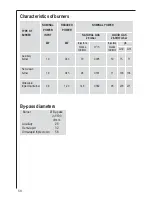
Page 10: ...jectors g h marks m3 h marks G30 G31 100 mm 100 mm Auxiliary burner 1 0 0 33 70 0 095 50 73 71 Semi rapid burner 1 9 0 45 96 0 181 71 138 136 Ultra rapid triplecrownburner 3 8 1 20 146 0 362 98 276 27...

Page 11: ...heapplianceandtheelectricitysupply withaminimumgapof3mm betweenthe switchcontactsandofatypesuitablefortherequiredloadincompliancewiththecurrentrules Theconnectioncablehastobeplacedinorderthat ineachpa...

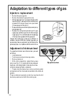
Page 12: ...le compared with the required pressure an appropriatepressureadjustermustbefittedonthe gassupplypipe incompliancewiththerulesinforce Adjustmentofminimumlevel Toadjusttheminimumleveloftheburners procee...

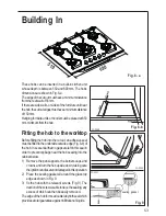
Page 13: ...anadhesiveseal mustbefittedtotheundersideoutsideedge Fig 8 b of thehob Itisessentialthatnogapsareleftinthissealin ordertopreventspillagenearthehobseepingintothe cabinetbelow 1 Remove the pan supports...

Page 14: ...en in designing the forniture unit in order to avoid any contact with the bottom of the hob which can be heated when it is operated The recommended solution is shown in Fig 10 The panel fitted under t...

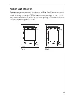
Page 15: ...rackets to allow a continuous supply of air To avoid overhating the building in should be carried out as shown in Figs 13 e 14 The hob s electric connection and the oven s one must be carried out sepa...

Page 16: ...s No 1 choice The Electrolux Group is the world s largest producer of powered appliances for kitchen cleaning and outdoor use More than 55 million Electrolux Group products such as refrigerators cook...

Reviews: