UPS IST7 Series (60K-200K)
User Manual
3 Installation
63
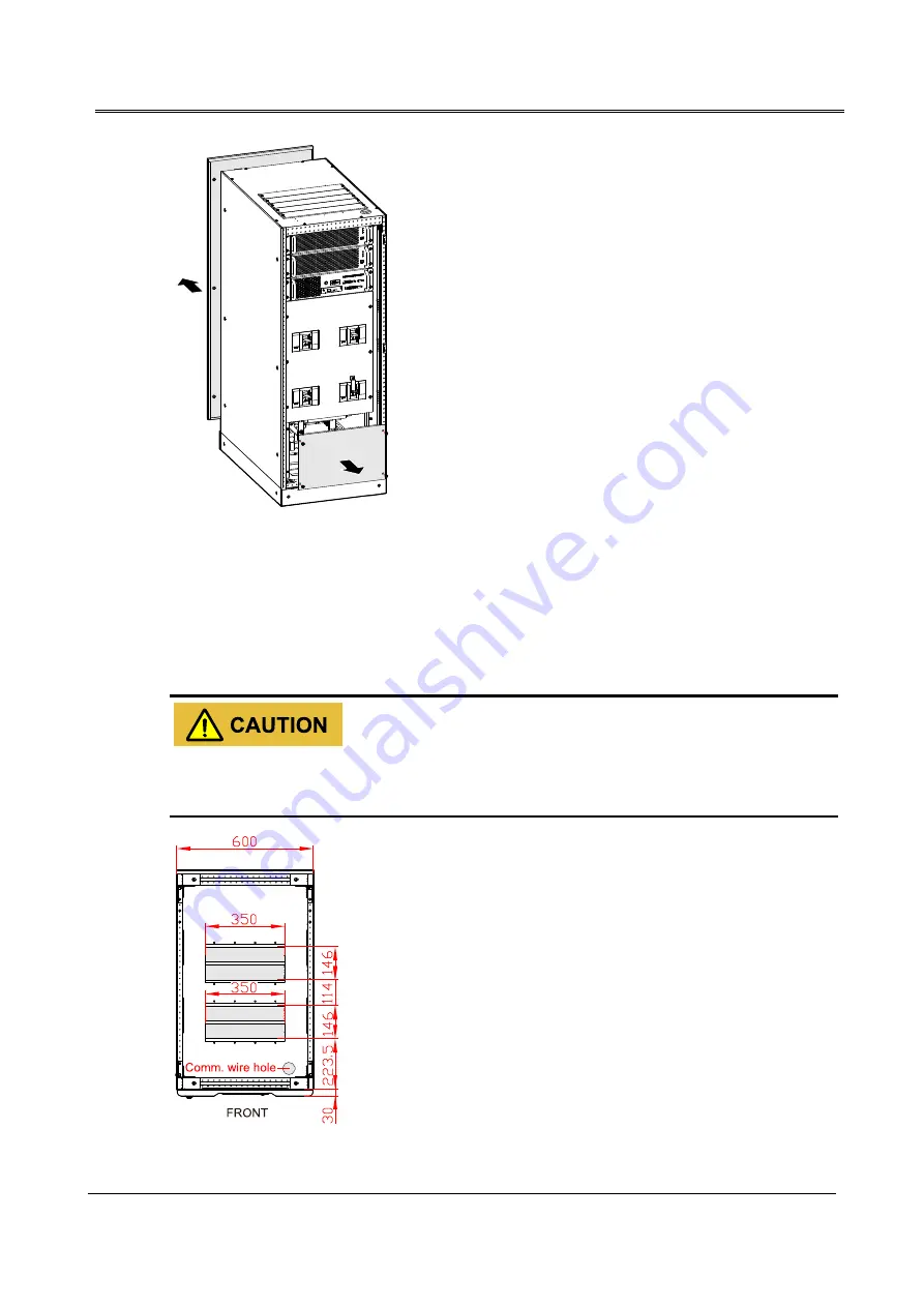
Figure3-33
Remove the back and top wiring cover plate of IST7-160, IST7-200
Step 2
Lead the input cables, output cables, battery cables and PE go through the top wiring hole(the position
of wire inlet and outlet holes as shown in Figure3-34), and connect the wiring terminal respectively(the
wiring terminal as shown in Figure3-35, Figure3-36), then fasten the bolts.
When wiring, ensure that the connection between input/output wire and input/output terminal is reliably,
avoid bad connection or wrongly connection.
Figure3-34
Wire inlet and outlet hole of down wiring of IST7-160, IST7-200
Summary of Contents for IST7 Series
Page 1: ...UPS IST7 60 200kVA Series User Manual www aecups com ...
Page 2: ......


