background image

085501390f  

7  

Installation

 Danger!

Improper installation will 

cause explosion!

Do not install signal tower in 

areas where there is hazard of 

explosion!

Failure to follow this instruc-

tion will result in death or 

serious injury.

Operate the signal tower only 

at temperatures between  

–25 °C and +50 °C

 Danger! 

Hazardous voltage!

Installation of electrical system 

must be executed by special-

ists only!

Electric shock will result in 

death or severe injury.
All circuits must have a 

common disconnect and are 

to be connected to the same 

pole of the disconnect.
CAUTION:  

Please disconnect power 

before installation or servic-

ing!

The nominal voltage of the rel-

evant signal module must be 

in accordance with the supply 

voltage!
Protect signal tower externally 

against overload current.
24V DC: 

Protective low voltage  

(VDE 0100-410), safety trans-

former (EN 60742),or convert-

er (EN 61046) respectively 

required for connection.
115/ 230V AC: 

Make the electrical connection 

with a sheathed cable.

-/N

1+/L

3+/L

5+/L

4+/L

2+/L

AC:

DC:

PE

N

L

Se

gme

nt

-n

o.

2

3

4

5

1

+

-

N

o.

 m

ód

ul

de

 s

al

L

L

L

L

+

+

+

+

1

M

od

ul

-Nr.

N

o.

 s

eg

me

nt

 lu

m

in

is

cen

t

No. módulo de señal

No. segment luminiscent

Modul-Nr.

Segment-no.

71

54

50

5

4,5

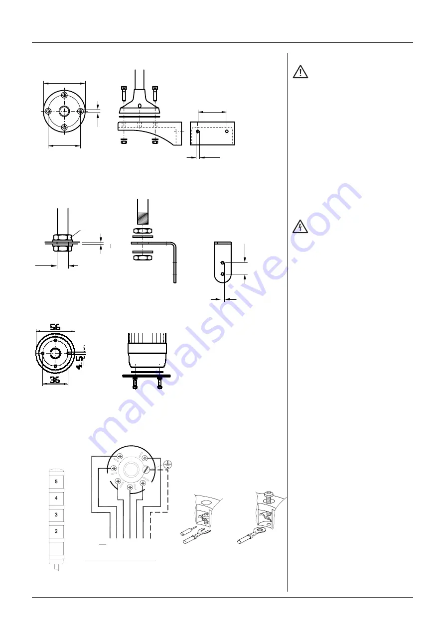
Stativmontage / Instalación de soport 

Montage sur socle / Support installation

Rohrmontage / Instalación en tuberías  

Montage sur tige / Pipe installation

Direktmontage / Instalación directa  

Montage direct / Direct assembly

Anschluss-Schema / Esquema de terminales 

Schéma de raccordement

 / Terminal scheme

M16x1,5

17

20

9

>1

∅ 

Zuleitung max. 1,5 mm²

∅ 

Línea de alimentación max. 1,5 mm²

∅ 

Câbles d’alimentation: section max. 1,5 mm²

∅ 

Supply line max. 1,5 mm²

Kabelanschluss: Drehmoment 0,6 Nm

Conexión de cable: Torque 0,6 Nm

Raccordement du câble: Couple 0,6 Nm

Wire connection: Torque 0.6 Nm 

Maße in mm/ Dimensiones en mm/ Dimensions en mm/ Dimensions in mm

BR50-BC 

BR50-BC-W 

  BR50-BC-WR

Summary of Contents for BR 50-CL

Page 1: ...RANCE Tél 33 0 5 59 06 06 00 Fax 33 0 5 59 06 44 www aet fr BR50 Montage und Wartungsanleitung 2 15 Signalsäule BR50 Manual de Instalación y Mantenimiento 2 15 Columna de señalización BR50 Manuel d installation et d entretien 2 15 Colonne lumineuse BR50 ...

Page 2: ... las cubier tas rojo amarillo naran ja verde azul incoloro blanco 3 bloque de contactos 4 soporte con pestaña 5 tornillo de cabeza cilíndri ca M4x20 4x 6 junta del soporte 7 arandela 4x 8 tuerca M4 4x 9 soporte roscado 10 tuerca M16 2x 11 arandela 2x 12 soporte en ángulo Liste des pièces détachées 1 Couvercle 2 Segment luminescent Versions Feu continu feu cligno tant flash Avec signal acoustique S...

Page 3: ...4 support with flange 5 cheese head screw M4x20 4 x 6 sealing for support assembly 7 washer 4x 8 nut M4 4x 9 threaded support 10 nut M16 2x 11 washer 2x 12 support angle Die Abbildung zeigt die Ausführung mit drei Signalmodulen La figura muestra el diseño con tres segmentos iluminados Le croquis montre un modèle à trois segments luminescents Figure shows design with three illuminated segments ...

Page 4: ... tuberías núm de pieza 28250230000 Interfaz y Módulos de seguridad Módulo AS i máximo de 4 módulos AS i 3 0 EN 50295 Luz fija LED monitoreado máximo de 3 módulos Salida de alarma max 230V 80mA RON max 35 Ω Accessoires 13 Jeu pour montage direct a Joint b Anneau 4x c Écrou 4 2x16 4x 15 Jeu de montage IP65 a Anneau pour seg ments luminescents et socle pour la douille 1 par segment 1 pour le socle Ré...

Page 5: ...tact carrier part no 28250220000 b O ring support only at support and pipe installation part no 28250230000 Interface and monitored modules AS i Module max 4 moduls AS i 3 0 EN 50295 monitored LED continuous light max 3 modules alarm output max 230V 80mA RONmax 35 Ω c screw 4 2x16 4x part no BR50D 14 wall support complete set only in connection with support assembly part no EQBR50 ...

Page 6: ...heridas graves La tensión nominal de la co lumna de señalización debe corresponder a la tensión de la alimentación Instale una protección exte rior de la columna de señali zación contra sobrecarga de corriente 24V CC Conexión solamente con ten sión minima protectora VDE 0100 410 o con transforma dor de seguridad EN 60742 o con conversor EN 61046 115 230V CA Realizar la conexión eléctrica con un ca...

Page 7: ...0 410 safety trans former EN 60742 or convert er EN 61046 respectively required for connection 115 230V AC Make the electrical connection with a sheathed cable N 1 L 3 L 5 L 4 L 2 L AC DC PE N L Segment no 2 3 4 5 1 No módulo de señal L L L L 1 Modul Nr No segment luminiscent No módulo de señal No segment luminiscent Modul Nr Segment no 71 54 50 5 4 5 Stativmontage Instalación de soport Montage su...

Page 8: ...o de la flecha deben coincidir las mar cas A y B 2 Instale el módulo de señal deben coincidir las marcas A B y C 3 Gire el anillo de bayoneta en el sentido de la flecha hasta que enganche el anillo debe enganchar 4 Instale el resto de los mó dulos de señal o la tapa Montage des segments luminescents Ne jamais monter plus que 5 segments Le segment de signalisa tion acoustique doit obli gatoirement ...

Page 9: ... only to be mounted at the top in stead of the cover 1 Turn bayonet ring in direc tion of arrow markings A and B must coincide 2 Install signal module markings A B and C must coincide 3 Turn bayonet ring in direc tion of arrow until it engag es ring must engage 4 Install further signal mod ules or cover ...

Page 10: ... la bom billa defectuosa gírela a izquierdas y desmóntela Peligro Energia Almacenada Después de desconectar la alimentaçion o del módulo espere 2 minutos para que se descarguen los condensado res antes de prestar servicio El incumplimiento de esta instrucción causará lesiones o daño al equipo 5 Instale la bombilla nueva respetando los valores de la potencia 6 Monte la columna de señalización Respe...

Page 11: ...modules 2 Loosen bayonet ring turn in direction of arrow 3 Remove signal module pulling in direction of ar row 4 Slightly push down de fective lamp turn it coun ter clockwise remove Danger Stored energy After disconnecting the pow er module wait 2 minutes for capacitors to discharge before servicing Failure to follow this in struction can result in injury or equipment damage 5 Install new lamp obs...

Page 12: ... Desmonte el módulo so noro 2 Seleccione el tono desea do 3 Instale el módulo sonoro 4 Compruebe el funciona miento Limpieza No use disolventes gasolina ni líquidos simi lares para limpiarla Limpie las superficies usando un paño humede cido Choix des tonalités suc cessives du segment acoustique Le segment acoustique est capable de produire diverses séries de tonalités Ce ré glage s effectuant au s...

Page 13: ...ti tion rate Inside the sounder module different tones may be set 1 Remove sounder module 2 Set desired tone 3 Install sounder module 4 Check function Cleaning Do neither use solvents petrol nor similar liquid for cleaning Clean surfaces using wet cloth ...

Page 14: ... 230V 50 60Hz 35 mA 7 W 115V 50 60Hz 65 mA 7 W Blitzlicht Luz de destellos flash Flash Flash light 24V AC DC 100 mA 0 85 Hz 1 25 Hz 2 4 W IP54 230V 50 60Hz 10 5 mA 0 6 Hz 2 0 Hz 2 5 VA 115V 50 60Hz 20 mA 0 6 Hz 2 0 Hz 2 5 VA Schallgeber Sonoro Signal acoustique Sounder 24V DC 12 mA 0 3 W IP 43 230V 50 60Hz 15 mA 3 5 VA 115V 50 60Hz 15 mA 1 8 VA LED Dauerlicht Luz fija LED Feu continu DEL LED Conti...

Page 15: ...d de tubería Hauteur de la tige Length of pipe Direktmontage Instalación directa Montage direct 100 mm 250 mm 400 mm 100 mm 250 mm 400 mm Direct assembly 1 183 mm 333 mm 483 mm 209 mm 359 mm 509 mm 107 mm 2 246 mm 396 mm 546 mm 272 mm 422 mm 572 mm 170 mm 3 309 mm 459 mm 609 mm 335 mm 485 mm 635 mm 233 mm 4 372 mm 522 mm 672 mm 398 mm 584 mm 698 mm 296 mm 5 435 mm 585 mm 735 mm 461 mm 611 mm 761 m...

Reviews: