background image


4.


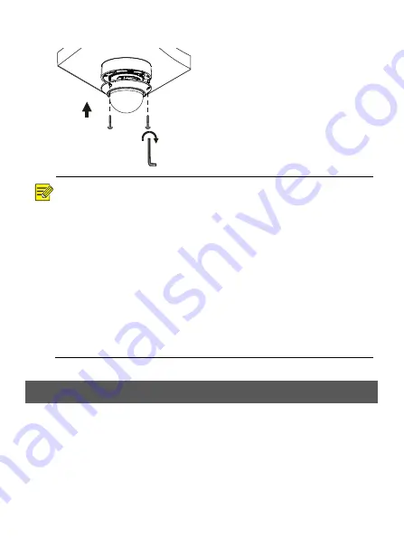
Mount the transparent dome cover. 

!


NOTE! 

l


The preceding installation process is concealed installation, during which holes 

are drilled in the ceiling and tail cable is led out from the top of the camera. 
Cables are connected and frapped at the ceiling side to prevent messy cables 

from affecting camera mounting. If open installation is adopted, tail cable is led 
out from one side of the camera and can be routed from the side groove of the 
camera. 

l


If necessary, wire the tail cables through pipes (for example 3/4 NPS threaded 

pipes), and screw the pipes into the threaded hole of the device to complete 
the connection. 

l


After mounting the dome housing, check that the two cross-recessed pan-head 

screws on the edge of the dome housing are tightened up to ensure that the 
camera  is  properly  sealed.  For  details,  see  Mount  the  transparent  dome 
housing. 


5


Startup 

After  you  have  installed  the  device,  connect  one  end  of  the  power  adapter 

(purchased  separately)  to  power  supply,  and  then  connect  the  other  end  to  the 
power interface to start up the device. 

Align the screw holes 

in the base, and 

tighten the three torx 

screws on the edge of 

the transparent dome 

cover to fix it.

Summary of Contents for M-87-V

Page 1: ...V1 00 Network Fixed Dome Cameras Quick Guide M 87 V...

Page 2: ...the cables l Use waterproof components to protect the network cable Waterproof the power cable separately if you don t use it The video cable does not need waterproof treatment 1 Use insulation tape...

Page 3: ...into the interface 5 Optional After the waterproof treatment is completed put the cables into a waterproof junction box purchased separately CAUTION l The cable connector must not be exposed and must...

Page 4: ...structions Installation and removal of the unit and its accessories must be carried out by qualified personnel You must read all of the safety instructions before installation and operation 2 1 Precau...

Page 5: ...ing mounting take off the dome cover and keep it away from dust Install the dome cover after the base is installed l Contact professionals for maintenance information Do not attempt to dismantle the d...

Page 6: ...nection The appearance and tail cable may vary with device model 1 Audio input Audio output GND 2 Alarm input IN GND Alarm output N P 3 Power interface 4 Ethernet interface 134 0mm 5 3 111 3mm 4 4 4 6...

Page 7: ...rt Micro SD Card Insert a SD card into the slot to use the local storage function For detailed specifications of recommended SD cards contact your dealer or technical support Hot plugging is not recom...

Page 8: ...e hole Use a 6mm 6 5mm drill bit to drill 30 mm depth guide holes according to the template Knock the plastic rivets into the guide holes and ensure that they are tightened up 1 2 1 Connect all cables...

Page 9: ...s through pipes for example 3 4 NPS threaded pipes and screw the pipes into the threaded hole of the device to complete the connection l After mounting the dome housing check that the two cross recess...

Page 10: ...eed to use the assigned IP address to log in l You may need to install a plug in at your first login Please follow the on screen instructions to complete the installation and then open the browser aga...

Page 11: ...e the collection of personal information such as face fingerprint license plate number email phone number GPS Please abide by your local laws and regulations while using the product About This Manual...

Page 12: ...ent allowed by applicable law in no event shall our total liability to you for all damages for the product described in this manual other than as may be required by applicable law in cases involving p...

Page 13: ...stalled serviced and maintained by a trained professional with necessary safety knowledge and skills Before you start using the device please read through this guide carefully and make sure all applic...

Page 14: ...tterie correctement Mauvaise utilisation de la batterie comme celles mentionn es ici peut entra ner des risques d incendie d explosion ou de fuite liquide de gaz inflammables Remplacer la batterie par...

Page 15: ...and EMC Directive 2014 30 EU WEEE Directive 2012 19 EU The product this manual refers to is covered by the Waste Electrical Electronic Equipment WEEE Directive and must be disposed of in a responsibl...

Reviews: