


The following is intended to provide some of the system configurations that are possible with the ADVEXL10 Overhead LED Backlit LCD Monitor
with DVD Player:
The ADVEXL10 has an option that allows the user to select from two IR transmit and receive codes (M1 or M2). This feature can be used when using
two ADVEXL10 units in the same installation or if the vehicle has an RSA (Rear Seat Audio) that uses an “A” channel headset. The ADVEXL10 comes
factory set to M1. When in the M1 mode the unit will respond to remote commands when M1 is selected on the remote and will transmit audio
on the A channel. When in the M2 mode the unit will respond to remote commands when M2 is selected on the remote and will transmit audio
on the B channel.
GENERAL SYSTEM CONFIGURATIONS (IR TRANSMIT AND RECEIVE MODES M1 OR M2)
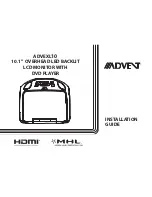
PICTURE
WFMM
SETTING
DEFAULT DVD
SCREEN MODE
MONITOR MODE
IR TRANSMITTER
LANGUAGE
FACTORY SETTING
ON
OFF
16:9
4:3
M1
M2
ON
OFF
EXIT
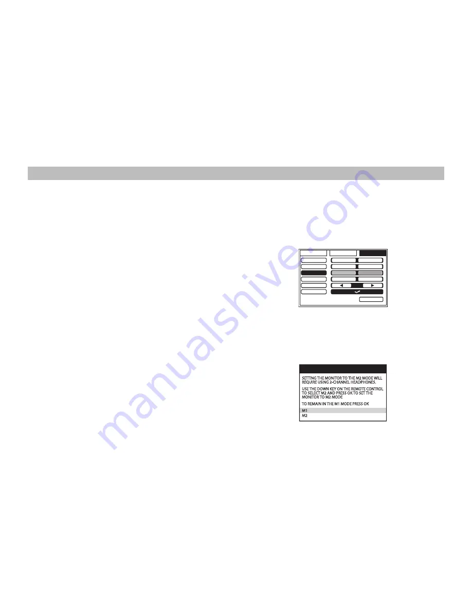
WARNING
SETTING THE MONITOR TO THE M2 MODE WILL
REQUIRE USING 2-CHANNEL HEADPHONES.
USE THE DOWN KEY ON THE REMOTE CONTROL
TO SELECT M2 AND PRESS OK TO SET THE
MONITOR TO M2 MODE
TO REMAIN IN THE M1 MODE PRESS OK
M1
M2
3
Selecting a Monitor Code (M1 or M2)
1.
Power ON the unit and wait until M1 or M2 appears on the OSD.
M1 or M2 will appear on the screen for 4~5 seconds.
2.
Press the System Menu button on the remote control to display
the system menu to change the monitor code from M1 to M2.
3.
Use the
t
or
u
cursor buttons to select the Setting sub menu.
4.
Use the
p
or
q
cursor buttons to select the Monitor Mode sub
menu option.
5.
Use the
t
or
u
cursor buttons to select the desired Monitor Mode
(M1 or M2), press OK to confirm the setting and the following
screen will appear.
6.
Use the
p
or
q
cursor buttons to change the selected Monitor
Mode (M1 or M2), press OK to confirm the setting.
7.
Press the System Menu button on the remote control to exit the
System Menu mode.
NOTE:
If no action is taken, this menu will disappear in 10 seconds.
The two overheads can be connected together using RCA cables plugged
into the AV Input and AV Outputs connectors.
•
Plug the AV OUT of the M1 unit into the AV IN of the M2.
•
Plug the AV IN of the M1 unit into the AV OUT of the M2.


