background image

Appendix A:  USB Driver Installation 

Advent Instruments Inc. 


Appendix A:  USB Driver Installation 

The WHQL certified driver files are automatically installed along with the TRsSim 
application and the following procedure should only be required if the end application 
will not use the TRsSim software.   

The drivers may be installed manually by using the add remove hardware wizard or via 
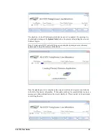
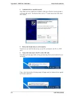
the self extracting installer package.  The following figures show the step by step 
procedure for installing the USB drivers with this installer package.   


1.  Download the USB installer Package 

The USB installer package can be downloaded from our website at the following page  

http://www.adventinstruments.com/Downloads/ or copied from the original CDrom 
provided with the instrument.   


22 

AI-5120 User Guide 

Summary of Contents for AI-5120

Page 1: ...Telephone Line Monitor AI 5120 User Guide Advent Instruments Inc Release 1 2d ...

Page 2: ...al that is connected to the functional ground of the instrument When the symbol is present it indicates that the surface may be hot Avoid contact with the surface of the instrument to avoid burns When the symbol is present near a screw it should be connected to a safety earth ground using a wire recommended in the User Guide Installation Categories Advent Instruments products are designed for use ...

Page 3: ...on the AI 5120 3 1 5 Connecting to the PC 4 2 TRsSim Software 6 2 1 Introduction 6 2 2 For More Information 9 3 AI 5120 Instrument Suite 10 3 1 Introduction 10 3 2 For More Information 12 4 Technical Overview 13 4 1 Block Diagrams 13 4 2 Indicators Connections 15 4 3 Specifications 18 5 Firmware Updates 20 Appendix A USB Driver Installation 22 Appendix B Error Codes 25 Appendix C Support 27 AI 512...

Page 4: ......

Page 5: ...s over 10 Mohm As such it has little to no effect on any signals present on the telephone line The supplied TRsSim PC software provides a high level graphical user interface for controlling the AI 5120 As events are detected the software displays timing and measurement information In addition waveforms for each event may be recorded for display and further analysis Waveforms can be played back to ...

Page 6: ...connection is strongly recommended due to the fast data transfer rates The Instrument Suite software requires the USB connection 1 2 Package Contents Use care when unpacking the AI 5120 to avoid damage to the instrument and the packing materials Retain the packing materials in case the unit is to be transported in the future Please inspect the shipping container and the contents for any damage If ...

Page 7: ...res If damaged is suspected do not continue to operate the instruments until inspected by qualified service personnel Caution To reduce the risk of fire use only a No 26 AWG or larger telecommunications line cord The instrument is intended for use in an indoor laboratory environment with an altitude not to exceed 2000m Pollution Degree 2 To clean the instrument disconnect it from the power supply ...

Page 8: ...C The AI 5120 can be connected to the PC by either its RS 232 port or USB 2 0 compliant full speed 12 Mbit second port Both connectors are present on the rear panel of the unit If using the TRsSim software with the AI 5120 the USB connection is strongly recommended because of its higher data rate USB incurs less latency when sending commands and receiving the waveform data from the AI 5120 However...

Page 9: ...able is required for the connection Do not use a cross over cable between the AI 5120 and the PC serial port The AI 5120 s RS 232 data transmissions are fixed at 8 data bits with 1 stop bit and no parity The baud rate is adjustable from a default at power up setting of 9600 bps to a maximum of 115200 bps If a break signal at least 11 consecutive space bits is detected by the AI 5120 it resets its ...

Page 10: ...rm may be recorded This information is then transferred to the PC where the TRsSim software is used to view and analyze the data Each recorded waveform can range up to 20 seconds in duration The TRsSim software can capture multiple waveforms encompassing a total monitoring time span of 1000 hours The graphical representation of the AI 5120 is the main control panel The TRsSim software can connect ...

Page 11: ... and information is provided by the Data Recorder window In the following figure portions of the captured waveforms for the Caller ID transmission are displayed The AI 5120 records waveforms using two different channels The first channel is DC coupled and provides a maximum range of 300 volts It is used for recording events such as ringing on hook off hook line flash and pulse dialing The second c...

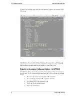
Page 12: ...t connector speaker output or any installed PC audio sound card Waveform Analysis Software Option AI ET003 The TRsSim software can include an optional component that provides more advanced analysis tools The Waveform Analysis option gives the TRsSim software the following abilities Show byte and bit level decoding of any FSK waveforms More detailed physical layer FSK signal measurements More detai...

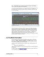
Page 13: ...ditionally the frequency spectrum during the mark interval is shown This is used to extract information about any potential interfering signals Finally the third portion of the report provides a listing of each data byte detected 2 2 For More Information Detailed information on the operation of the TRsSim software for the AI 5120 can be found in the TRsSim Telephone Line Monitor User Guide documen...

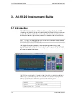
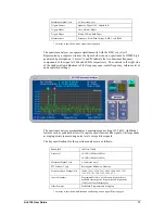
Page 14: ...are program and not part of the basic AI 5120 package The figure below shows an example of the oscilloscope capturing a DTMF digit generated by a telephone Similar to a conventional oscilloscope controls located at the right side of the window determine various settings such as vertical scale horizontal time base trigger conditions and cursors The DSO has a record depth of 5 seconds giving it the ...

Page 15: ...and acquisition settings The spectrum analyzer accommodates a maximum span setting of 35 kHz Additional features such as peak hold allow it to capture short transient like signals while spectrum averaging assists in measuring noise levels or repetitive signals The key specifications for the spectrum analyzer are as follows Bandwidth 100Hz to 35kHz Accuracy 0 2 dB 100Hz to 10kHz 0 5 dB 10kHz to 35k...

Page 16: ...ed with the software installation and can be accessed by selecting the User Manual command from the Help menu As newer versions of the Instrument Suite software are made available they are posted on our web site at http www adventinstruments com Along with software updates the web site also contains the latest versions of any relevant documentation For technical support regarding the AI 5120 or th...

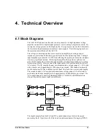
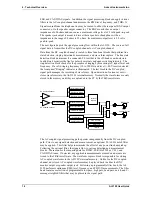
Page 17: ...followed by analog to digital conversion However one of the signal paths is DC coupled while the other is AC coupled The DC coupled channel can accommodate a voltage range of 300 volts with a sample rate of approximately 1200 sample per second This channel is primarily used for detecting DC line conditions on off hook line flash line reversals and ringing The second channel is AC coupled with a ma...

Page 18: ...ock in the DC coupled signal path manages the recording of waveforms Upon detection of various events it stores waveforms into the AI 5120 s internal memory Normally the waveforms are only stored in the memory until they are uploaded to the PC by the TRsSim software Line State Detection Internal Memory BNC Output Prog Filters RMS Level Freq Counter THD N DC Coupled Channel Ring Det Meas Waveform C...

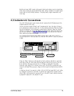
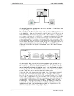
Page 19: ...ator briefly flashes anytime data is either sent to the PC or received from the PC Data transferred on either the USB or RS 232 causes the indicator to flash Communication Ready Off Hook Ringing Line Bypass Unit Ready Communication with Host Ringing Detected Terminal Equipment Off Hook RJ 11 Connectors Tip Ring Interface 300 V Peak CAT I When the Ready indicator is illuminated no fault condition t...

Page 20: ...ts Inc www adventinstruments com Made in Canada The BNC output connector can be used to monitor signals from the telephone line Its source impedance is 600 ohms with a maximum output level of 5 Volts peak to peak The 3 mm mono speaker jack to the left of the BNC monitor output performs a similar function and can drive a speaker or headphone directly The load impedance should be in the range of 8 t...

Page 21: ...nd labor warranty period for another year to a total of two years from date of purchase on the instrument AI K003 Additional Three Year Warranty The standard product support and warranty period for the instruments is one year This option increases the parts and labor warranty period for another three years to a total of four years from date of purchase on the instrument AI 5120 User Guide 17 ...

Page 22: ...s at 16 bits sample Input Output BNC Output Unbalanced Ground Referenced Output Impedance 600 Ω 3 Output Level 5 Vp p Maximum Frequency Range 10 Hz to 18 kHz Frequency Response 0 2 dB 50 Hz to 10 kHz Signal Source Tip Ring Tip Ring with user selectable filters Speaker Output Unbalanced Ground Referenced Output Level 2 8 Vp p Maximum Load Resistance 8 Ω to 32 Ω Frequency Range 100 Hz to 18 kHz Freq...

Page 23: ...cation Equipment RS 232 Connector 9 pin D style connector AC Line Voltage 100 to 240 Vrms Frequency 50 to 60 Hz Physical Dimensions Width 14 cm 5 5 Height 4 cm 1 6 Depth 20 cm 8 0 Weight 680 g 1 lbs Operating Temperature Range 5 to 40 ºC 80 RH Storage Temperature Range 25 to 70 ºC 80 RH Operating Altitude 2000 m AI 5120 User Guide 19 ...

Page 24: ...installed on a PC connect the AI 5120 to one of its COM ports Power the AI 5120 on and start the firmware update software The software will ask if it should query our website for latest updates It is recommended to click yes to ensure the latest firmware is utilized Once the update if available is downloaded the software checks for all compatible devices connected to the PC Once this is complete a...

Page 25: ...to shut off the power during the update process as this may permanently corrupt the memory of the device Once the update process is complete and no errors were detected a green icon is shown to the left of the device information If the update could not be completed due to errors a message providing information on the error is displayed Please contact us for assistance in resolving the error AI 512...

Page 26: ...oftware The drivers may be installed manually by using the add remove hardware wizard or via the self extracting installer package The following figures show the step by step procedure for installing the USB drivers with this installer package 1 Download the USB installer Package The USB installer package can be downloaded from our website at the following page http www adventinstruments com Downl...

Page 27: ... computer double click on the file to start the self extraction and the following window will be displayed 3 Click on the Next button to install the driver files Windows will now copy the driver files from the installer package to the target computer AI 5120 User Guide 23 ...

Page 28: ...oth of the listed driver names 5 Click on the Finish button to exit the installer The driver is now installed and you may connect the instrument to the PC via a USB cable 6 Connect the Instrument to the PC via the USB cable The following brief popup bubble will appear indicating Windows has detected the new instrument Then a short time later the following popup will appear and the instrument is re...

Page 29: ... once after the last calibration execute it again It should be able to restore the missing data If not please contact technical support for assistance 1005 Flashing Off Off Flash Memory Corruption No Program File The primary DSP application program is missing from the flash memory or is corrupted Use the Ai5120Update exe program to restore the flash memory contents n a Flashing Flashing Flashing F...

Page 30: ...normal operation Please contact technical support if this error occurs It represents a software problem and should be corrected n a The following error code is a special case in which the Ready indicator is not flashing This error can only occur shortly after the AI 5120 is powered on READY Indicator RINGING Indicator OFF HOOK Indicator Description Corrective Measure Error Code Off Off Off Flash M...

Page 31: ...nstruments com Sales Inquires sales adventinstruments com In North America Tel 604 944 4298 Fax 604 944 7488 Mail Advent Instruments Inc 111 1515 Broadway Street Port Coquitlam BC V3C6M2 Canada In Asia Tel 852 8108 1338 Fax 852 3909 2338 Mail Advent Instruments Asia Ltd Unit 42 18 F Block D Wah Lok Industrial Centre Phase II 31 35 Shan Mei Street Fotan Shatin New Territories Hong Kong AI 5120 User...

Page 32: ... halogenated flame retardants such as PBB and PBDE in electrical and electronic equipment Advent Instruments products will have less than the RoHS limits stated below for the six restricted use substances Restricted Substance List Substance Maximum Limit Weight Cadmium Cd 100 ppm Lead Pb 1000 ppm Mercury Hg 1000 ppm Hexavalent Chromium Cr6 1000 ppm Polybrominated Biphenyls PBB 1000 ppm Polybromina...

Reviews: